Hi Salas,
Two questions:
Is there any reason not to use MUR860 diodes on the new blue hypno boards if I have some spare? They are also 8A 200volt fast recovery and the package size is the same.
Where do I look for a guide to implementation of the shunt reg only for different voltages, like 27v (to drive my Atlantic RIAA), for example?
Many thanks
Lucas
For guide you look in post 1, this thread.
There is no reason you can't use any proper diode you have.
There is no reason you can't use any proper diode you have.
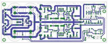
For single rail use, I realise that the central bar is a common earth, and that I need populate the + side only, but it's not so simple at the PS caps and rectifier diodes, which span across the two sides of the reg.
Do I need to add a jumper from the - side to earth to complete the rectifier circuit?
Do I need to add a jumper from the - side to earth to complete the rectifier circuit?
Hi Lucas,
as v+ PS, only two caps need to be on the side with IRFP9240's are populated.
All four diodes should be used for full phase rectification.
J2, J3 can be skipped, J1 needs to be used.
as v+ PS, only two caps need to be on the side with IRFP9240's are populated.
All four diodes should be used for full phase rectification.
J2, J3 can be skipped, J1 needs to be used.
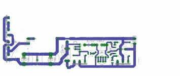
Sorry, stupid question. I realise what I need to do now. I have cut the board traces to leave this:
http://www.diyaudio.com/forums/attachment.php?attachmentid=183902&stc=1&d=1281696710
Seems such a waste of PCB. Maybe I should've p2p-ed it.
Thanks
http://www.diyaudio.com/forums/attachment.php?attachmentid=183902&stc=1&d=1281696710
Seems such a waste of PCB. Maybe I should've p2p-ed it.
Thanks
Attachments
Hi Lucas,
as v+ PS, only two caps need to be on the side with IRFP9240's are populated.
All four diodes should be used for full phase rectification.
J2, J3 can be skipped, J1 needs to be used.
Hi Mr T
Thanks for that. I am up to speed. I think I'll skip J1 too and feed directly to the other end.
Is your trafo centre tapped 3 wire secondary or 2 wire? What are its specs?
Arrange for a config like in the attachment.
Thanks Salas. I have a dual secondaries on this particular toroidal transformer.
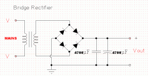
I am familiar with the schematic for a standard rectification pattern, but only a little confused as to how this relates to the PCB for single rail use.
Because one side is left unstuffed, it looks like the rectifier needs a jumper or two to complete the circuit. No?
Thanks again,
Lucas
OK will have a look in the connections of the new board for one side only request and will add some marks on it for you. Only give me a bit of time.
Thanks Salas
Meanwhile, I have another question. I have 2x Panny FC 2200uF 50V caps. Any good for the shunt supply or too small? The RIAA is Class A and will only pull about 20-30mA (estimated by your good self if I remember correctly, some time ago.)
Also, is there any advantage to the Hot-Rod for a phono stage?
Sufficient caps. There is quality gain in 200mA. Stay with 10R 5W and sink the Mosfets. You will need lytic in the bypass bay with resistor you gonna add for 27V. There are +/- marks. When only LEDS for 10V DCB1 use, PP cap benefit plays. Resistor Vref Vout extension calls for lytic due to different impedance needs.
2200uF is usually considered good enough for about 1A of DC current with tolerable ripple on the supply.
If you want excellent ripple on the supply you could reduce the current draw by a factor of 10, i.e. 100mA of DC current.
Set your CCS to 100mA and use 20 to 30mA at the RIAA. The remaining 70 to 80mA is dissipated in the regulator.
If you want excellent ripple on the supply you could reduce the current draw by a factor of 10, i.e. 100mA of DC current.
Set your CCS to 100mA and use 20 to 30mA at the RIAA. The remaining 70 to 80mA is dissipated in the regulator.
even with one 2200uF supplying 200mA, that is still five times as much capacitance per ampere as is usually used.
Plus the CCS firewalls ripple, but we spare no strategies in keeping away from stronger transients when cycle loading the caps so to avoid inviting more aggressive switching gremlins in the outer loop poking their dirty noses around. Academically speaking.🙂
Oh, my transformer is 25v x2 and rather too large 120VA.
With your centre tapped transformer, things are easy. Lending nicely to full wave two diode rectification for a positive polarity reg only you requested, without hacking the board. Reminder: Its either the big or small size diode pair you will use, not both.
Attachments
- Status
- Not open for further replies.
- Home
- Amplifiers
- Power Supplies
- Using the HYPNOTIZE as a general shunt reg PCB


