Your quote is not altogether correct as that text refers to AD844, not AD811.
Parallel AD844s should have lower noise, but THD improvement is doubtful although lower input impedance may help. Costwise hard to see the point especially compared to the discrete BJT IV.
Parallel AD844s should have lower noise, but THD improvement is doubtful although lower input impedance may help. Costwise hard to see the point especially compared to the discrete BJT IV.
Hmmm....should I be worried?It looks fine, good luck with your TDA1541 implementation!
I have eight unused 844s if anyone wants them for a small fee. I went down the Sowter I/V transformee route for my dual 1541 dac,

Hmmm....should I be worried?
Are you worried about becoming worried?
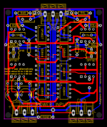
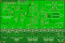
Hi Guys, here is my work of these days available to the community.
The dimensions are 62 x 69 mm and I have also planned the use of silver mica capacitors ith only two 1206 smd capacitors.
I hope I did everything right, obviously any advice is welcome.
You will also notice some strange and seemingly insignificant pads, don't worry, they are put there to be able to use the card in plug-in mode for my Philips CD960.
This is my gift for the epiphany, I hope it is appreciated.
Antonio
Attachments
Well...maybe because I read that more than three ad844 would be needed for TDA1541?🙄Are you worried about becoming worried?
Your quote is not altogether correct as that text refers to AD844, not AD811.
Parallel AD844s should have lower noise, but THD improvement is doubtful although lower input impedance may help. Costwise hard to see the point especially compared to the discrete BJT IV.
Sorry didn't look hard enough. But yes things do improove for the better when the 844 are stacked "without feedback", Barrie Gilbert AD's designer of the 844 agreed with that 5 years ago.
Quote from 2019:I was conversing with Barry Gilbert the designer of the AD844, he was very chuffed to see what we're doing with it without feedback and stacked for I/V stage. He was going to send me the proper schematic of everything inside it if he could find it, but he never did.
Cheers George
Hi Guys, here is my work of these days available to the community.
The dimensions are 62 x 69 mm and I have also planned the use of silver mica capacitors ith only two 1206 smd capacitors.
I hope I did everything right, obviously any advice is welcome.
You will also notice some strange and seemingly insignificant pads, don't worry, they are put there to be able to use the card in plug-in mode for my Philips CD960.
This is my gift for the epiphany, I hope it is appreciated.
Antonio
Attachments
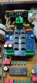
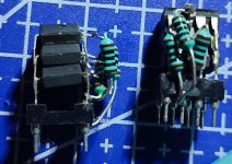
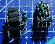
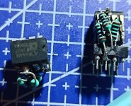
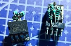
I went through my projects and found a perfboard with two "stacks" of AD844. There was also two 2SK170 and a trimpot for each jfet. It's been soo long since I made it, I don't know what schematic it was based on. Please post the schematic if anyone recognizes the stacks of AD844 and the description of the circuit 😅
IIRC it was to be an I/V board.
TIA 🙂
IIRC it was to be an I/V board.
TIA 🙂
Attachments
But the R1 TDA does not match the rest of the effort put in that DAC as it is the worst grade.Nice work on the PCB for the multi stacked 844's
If you feed an open loop AD844 from a PCM1704, resulting in 50 ohms input impedance, isn't that the near equivalent of a 50 ohms passive conversion?
Near equivalent because the resistor has a better pulse response.
How about 50 ohms, lowpass filter, gainstage 20x, buffer ?
Near equivalent because the resistor has a better pulse response.
How about 50 ohms, lowpass filter, gainstage 20x, buffer ?
Interesting unit variation (dac pcm63-K), using the pin 5 I/V from this thread, buffer opa1656. Some seem to be just naturally canceling out their 3rd and 4th harmonic.
Here are some of the common sample variations i found. But all of them have same gain, same good offset etc... But the spectrum is wildly diffrent.
If you have 2 singles you might have totally different spectrums on each channel. i think when stacking it averages out, and improves drastically starting at 2 stack, lessening with each next.
2 chips parallel

3 chips parallel

4 chips

Basically:
1 chip : 0.05
2 chio : 0.02
3 chip : 0.006
4 chip : 0.005
...
I suspect though because PCM63 is only 2mA, once bias starts being more than enough you stop seeing much gains. For weaker DAC maybe even 2-3 would be sweet spot.
For PCM1794, sky is the limit i guess...

3 chips parallel
4 chips
Basically:
1 chip : 0.05
2 chio : 0.02
3 chip : 0.006
4 chip : 0.005
...
I suspect though because PCM63 is only 2mA, once bias starts being more than enough you stop seeing much gains. For weaker DAC maybe even 2-3 would be sweet spot.
For PCM1794, sky is the limit i guess...
- Home
- Source & Line
- Digital Line Level
- Using the AD844 as an I/V