I don't understand the op amp circuit symbol with two internal current sources (Pre-Output-Driver) - go also to Fig. 29 on page 12 underCircuits of opa1612 and opa1642
https://www.ti.com/lit/ds/symlink/o...=https%3A%2F%2Fwww.ti.com%2Fproduct%2FOPA1612
How looks this area in detail ?
the mentioned TI op-amps OPA860/OPA861 in post #19 underReplacements for AD844/AD846
check out post #5 under
Choosing of best sounding OP AMPs for the lowest possible THD+N -really the best Way?
https://www.diyaudio.com/community/threads/i-v-and-analog-output-stage-for-ad1862.299414/
seems to be the closest to the AD844; but to judge it clearly one would need the internal circuit, which is missing as usual with TI - go to the datasheet under
https://www.ti.com/lit/ds/symlink/opa861.pdf
Last edited:
I have been using the triple AD844 IV with my miro AD1862 DAC and have been very happy with the results. I would like to build one to use the miro PCM63 DAC that I have but wanted to know if I need to change the value of R9 to something like 750 to 1500 ohms?
Also, can I use SparkOS opamps in place of the OPA627s? I have them and just don't want to pay the price to get another pair.

Also, can I use SparkOS opamps in place of the OPA627s? I have them and just don't want to pay the price to get another pair.
I don't understand the term "triple AD844". Means this three AD844 in parallel mode ?
Maybe this is a good replacement for the obsolet AD844:
https://www.diyaudio.com/community/...urrent-mirror-iv-converter-a-la-ad844.360162/
Who have heard against the AD844 ?
Maybe this is a good replacement for the obsolet AD844:
https://www.diyaudio.com/community/...urrent-mirror-iv-converter-a-la-ad844.360162/
Who have heard against the AD844 ?
I have been using the triple AD844 IV with my miro AD1862 DAC and have been very happy with the results. I would like to build one to use the miro PCM63 DAC that I have but wanted to know if I need to change the value of R9 to something like 750 to 1500 ohms?
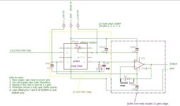
PCM63 gives twice the output current of AD1862 (+/-2mA against +/-1mA) so yes R9 should reduce to 1k3 (nearest value to half 2k7). However the OPA627 stage has 6dB gain - I would reduce that to 0dB by deleting R5 and reducing R3 to 150ohm. I can't quite see the point of putting in gain to give max 4VRMS output only to reduce it later prior to the poweramp.
I would guess Sparkos opamps would substitute OK for OPA627s but no direct experience of them myself.
P.S. to keep the filtering the same C34 should be increased to 1nF.

In my experiences using the AD844 as an IV, adding a 50 to 100 Ohm resistor between pin 5 and C34 can inhibit oscillations if the power supplies are questionable. I suspect this is caused by the output stage of the AD844 having the middle of the diamond actively driven in order to maximize the slew rate. It seems best if the input source impedance to the output diamond is 50 to 100 Ohms to ground as shorted through C34. It can also help to minimize parasitics at the Tz node from appearing broadband on C34 leading into the buffer.
Thank you. That is very helpful.PCM63 gives twice the output current of AD1862 (+/-2mA against +/-1mA) so yes R9 should reduce to 1k3 (nearest value to half 2k7). However the OPA627 stage has 6dB gain - I would reduce that to 0dB by deleting R5 and reducing R3 to 150ohm. I can't quite see the point of putting in gain to give max 4VRMS output only to reduce it later prior to the poweramp.
I would guess Sparkos opamps would substitute OK for OPA627s but no direct experience of them myself.
P.S. to keep the filtering the same C34 should be increased to 1nF.
looks good. I would add a shielding envelope for the buffer tube (for reducing thermal stress on the electrolytics around it - which is mainly caused by radiant heat of the tube).
The soxket for the ad844 is surely harming but all the mix should sound good according the ecc88 pedigree....
Cool setup.
Cool setup.
HI Abraxalito what does mening deleting R5, simply pull out to the PCB?PCM63 gives twice the output current of AD1862 (+/-2mA against +/-1mA) so yes R9 should reduce to 1k3 (nearest value to half 2k7). However the OPA627 stage has 6dB gain - I would reduce that to 0dB by deleting R5 and reducing R3 to 150ohm. I can't quite see the point of putting in gain to give max 4VRMS output only to reduce it later prior to the poweramp.
I would guess Sparkos opamps would substitute OK for OPA627s but no direct experience of them myself.
P.S. to keep the filtering the same C34 should be increased to 1nF.
in this case why R33 must be 150R value?
Is possible to use only R13 trimmer for handlyng general offset?
I would be able to avoid also R14 for one only use of trimmers?
Thanks
Antonio
what does mening deleting R5, simply pull out to the PCB?
Yes, precisely. Remove it from the circuit completely.
in this case why R33 must be 150R value?
Just because leaving 1k in circuit would create a lowpass filter with the 1k and the input capacitance of the opamp which reduces its stability. Instead of lowering R33's value you could leave it in circuit and parallel it with a capacitor, say 220pF. That might be more convenient as adding components is normally easier than exchanging them.
Is possible to use only R13 trimmer for handlyng general offset?
I would be able to avoid also R14 for one only use of trimmers?
I think only R13 is needed for offset trimming as the two stages are DC coupled.
If there is, it's a good sounding one 👍Is there any distortion measured of AD844 as used here ?
Cheers George
Here is one measurement of AD844 used in I/V:Is there any distortion measured of AD844 as used here ?
https://www.diyaudio.com/community/threads/dac-i-v-measurements.395738/post-7266906
H
HAYK
Very interesting comparative. Is the AD844 used as CFA opamp in closed loop or just OTA part in open loop?
- Home
- Source & Line
- Digital Line Level
- Using the AD844 as an I/V