Yes I am at the moment but at least it's not trying to do I/V which I think has the more impact on if it's an opamp or not.
But later I will try something discrete I have here ready made (attached) straight off the TZ pin if I know it's not going to load down the TZ output.
Let me know what you think.
Hi George
Did you actually try this discrete buffer after Tz pin? How did it sound? I like the simplicity of this circuit.
Hi George
Did you actually try this discrete buffer after Tz pin? How did it sound? I like the simplicity of this circuit.
Yes I did, it was OK, but the BUF03 was better.
The AD844's buffer/s was smoother even stacked but didn't have the dynamics of the BUF03.
Best was the OPA627, had almost the dynamics of the BUF03, yet was smooth and nicely separated still like the AD844 buffers.
Cheers George
Thanks George
It seems that the opa627 is a must try then. do you have a schematic? do you have additional LPF with it?
It seems that the opa627 is a must try then. do you have a schematic? do you have additional LPF with it?
I'd recommend a fully discrete solution for I/V - I've had excellent sonic results with building a CFB amp but rather than being fully symmetrical using current-source biassing to maintain classA operation. I have a sample schematic on my blog - http://www.diyaudio.com/forums/blogs/abraxalito/1283-discrete-transistor-based-cfb-i-v-stage.html
I now can't go back to opamps....
I now can't go back to opamps....
Thanks George
It seems that the opa627 is a must try then. do you have a schematic? do you have additional LPF with it?
Ran it on the same +-15vdc that the AD844's run off, in the Cary.
Just made the input impedance 200kohm, gave it 2 x gain, and put a cap across the feedback resistor to limit HF to -3db at 150khz, and had a 50ohm output resistor.
Cheers George
Pedja Rogic DDNF circuit boards
Update: I have 3 DDNF boards built up minus bipolar transistors. A friend asked me to build his Chinese transistor tester for him. Side benefit is I can try it out. Hope to get that done by the weekend. 2 boards will go in the Mark 3 Parallel TDA1541A S1 Crown dac. The other is slatted to go in the PCM1704 dac. I am only going to DC couple the PCM1704 version if at all possible. The unknown is if the Chinese device is accurate or not. Time will tell.
Update: I have 3 DDNF boards built up minus bipolar transistors. A friend asked me to build his Chinese transistor tester for him. Side benefit is I can try it out. Hope to get that done by the weekend. 2 boards will go in the Mark 3 Parallel TDA1541A S1 Crown dac. The other is slatted to go in the PCM1704 dac. I am only going to DC couple the PCM1704 version if at all possible. The unknown is if the Chinese device is accurate or not. Time will tell.
Parallel TDA1541A S1 Crown DAC experiment
Only have 2 of the S1 Crown's and a PCM1704. The S1's are real and I have had them since around 1990. Hard to remember the exact year. 🙂You have 3 x S1 ! Lucky guy 🙂
Chinese Transistor tester
Update: Tester works after doing the calibration. Now I know what the extra capacitor was for. Tested 65 transistors. I was right in one regard. Sticking to one brand yielded more closer matching parts. hfe or Beta on the NPN's came in at 601.3 on average with Vf (Voltage forward) which looks like vbe to me 0.659 VDC with a 0.001 VDC mismatch. hfe or Beta for the PNP's came in at 591.2 on average with Vf at 0.649 VDC with a slight spread of 0.002 VDC mismatch. So it looks like the NPN's are slightly stronger on current gain. It would seem that attempting super matching is likely a waste of effort here. I have to few transistors to get 6 super matched transistors. I will likely retest today to see how repeatable it is. Likely this is a good enough scenario to build the PCM1704 version and to look at that transistor thermal bonding issue. 😀
Update: Tester works after doing the calibration. Now I know what the extra capacitor was for. Tested 65 transistors. I was right in one regard. Sticking to one brand yielded more closer matching parts. hfe or Beta on the NPN's came in at 601.3 on average with Vf (Voltage forward) which looks like vbe to me 0.659 VDC with a 0.001 VDC mismatch. hfe or Beta for the PNP's came in at 591.2 on average with Vf at 0.649 VDC with a slight spread of 0.002 VDC mismatch. So it looks like the NPN's are slightly stronger on current gain. It would seem that attempting super matching is likely a waste of effort here. I have to few transistors to get 6 super matched transistors. I will likely retest today to see how repeatable it is. Likely this is a good enough scenario to build the PCM1704 version and to look at that transistor thermal bonding issue. 😀
Pedja Rogic DDNF for PCM1704
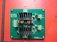
Assembled the DDNF board for the PCM1704. Untested as an assembly. My solution to bonding the transistors was video card double sided heatsink tape. I had some suitable heatsinks in my parts box. Hope to test it this weekend. Plan: Test offset and drift with shorted inputs. Test the DC coupled concept. It is essentially a go, no-go test. 🙄
Assembled the DDNF board for the PCM1704. Untested as an assembly. My solution to bonding the transistors was video card double sided heatsink tape. I had some suitable heatsinks in my parts box. Hope to test it this weekend. Plan: Test offset and drift with shorted inputs. Test the DC coupled concept. It is essentially a go, no-go test. 🙄
Attachments
Hi,
What's the dc offset of your highly matched DDNF? I found AD844 has minimum DC offset followed by OPA861 ( can be trimmed externally). These two are the easiest to build.
What's the dc offset of your highly matched DDNF? I found AD844 has minimum DC offset followed by OPA861 ( can be trimmed externally). These two are the easiest to build.
Pedja Rogic DDNF for PCM1704
The board test was somewhat what I expected. It did not like being shorted at the inputs however was unharmed. Without the PCM1704 connected I got +26 mV's and +32 mV's in each channel. Discrete is much tougher to get perfect. Does not have the benefit of laser trimming during manufacturing. Only positive thing was that at least in initial testing it was stable and had no drift. I am unsure if the BUF03 nulling circuit can correct that much offset. It would seem the capacitor should be used. I found a benefit to buffering the DDNF just like with the AD844. That avoids the 10 uF cap and the loss of bass depending on load. Will need a day or so to connect it to the dac and remeasure it.Hi,
What's the dc offset of your highly matched DDNF? I found AD844 has minimum DC offset followed by OPA861 ( can be trimmed externally). These two are the easiest to build.
+26 mV and +32 mV is still less than my OPA861 which often shows 20mv~50mv offset. Some say discrete version is better, but it really takes time to find good match pairs. Thanks to the many experts here, both my AD844 & OPA861 sound very good. I wonder if it's worth making a DDNF.
Pedja Rogic DDNF for PCM1704
I appreciate your input on the offset. I will try to get it hooked up tomorrow morning and retest it. Yesterdays test was to see what contribution any transistor mismatch would have on the DC offset. Both of my PCM1704's measured 0.1 mV's although the DMM is likely not to be trusted at that low level. If it is well behaved on the output of the dac I will attempt to null it out at the BUF03. It would be nice to skip the caps. As George says best cap is no cap. In my experience the DDNF with a film and foil cap and voltage buffer does out perform the AD844 triple stack. I have not tried the OPA861. I will have to do some testing however if it works with the PCM1704 I will let everyone know here on the thread. 😉+26 mV and +32 mV is still less than my OPA861 which often shows 20mv~50mv offset. Some say discrete version is better, but it really takes time to find good match pairs. Thanks to the many experts here, both my AD844 & OPA861 sound very good. I wonder if it's worth making a DDNF.
I can't remember if I've posted this excerpt from Stereophile review up on the Charles Hansen designed Ayre CX-7 CDP, so here it is again, sounds to me like he may be stacking as well.
"The PCM1738's analog outputs are in the form of current and appear to be fed directly to Analog Devices AD844 chips. This is a high-speed (2000V/µs!), low-settling-time bipolar op-amp optimized for current/voltage applications. Eight AD844s are used for the direct-coupled analog output stages. Although there are no coupling capacitors, no DC servo circuits are used; Ayre's Charles Hansen feels that this seat-of-the-pants approach optimizes low-frequency quality. Ayre also claims that the circuitry is "zero-feedback." Not only is there no loop voltage negative feedback, there are not even current feedback loops around the op-amps"
Cheers George
Last edited:
Strange to me all the focus on 'zero feedback' for the analog stages when the PCM1738 has oodles of it inside its digital modulators.
Strange to me all the focus on 'zero feedback' for the analog stages when the PCM1738 has oodles of it inside its digital modulators.
I believe it is more to do with I/V stage rather than output buffer.
As from what I've read and kind of understand it's the very HF noise and glitches that are so fast and short that are almost impossible to measure that come out of the dacs even the PCM1704 (which is said to be glitch free).
It's these noise/glitches that can upset I/V stages that have feedback, so to have the 844 with 2000V/us and have no freed back to get upset, is maybe the ideal condition for a stable I/V against the bombardment of noise and glitches from the dac/s. Just a thought.
Maybe that's why a simple I/V resistor is so liked, but has other major problems, with much gain needed after it which brings in much noise.
Cheers George
Last edited:
I suspect (though at present no measurements to support) that its using feedback in conjunction with a classAB output stage that's the issue for SQ. I have a discrete I/V with classA output stage and haven't noticed any problems, its using feedback.
The problem I've found from just using a resistor is its too sensitive to power supply noise - the PSRR of the DAC chip is best into either a short or an active short (as in an active I/V). A resistor can't give the same power supply rejection as an active stage. Hence I no longer use just a resistor for I/V, nor any classAB stage in my active I/V.
The problem I've found from just using a resistor is its too sensitive to power supply noise - the PSRR of the DAC chip is best into either a short or an active short (as in an active I/V). A resistor can't give the same power supply rejection as an active stage. Hence I no longer use just a resistor for I/V, nor any classAB stage in my active I/V.
Hi GeorgeRan it on the same +-15vdc that the AD844's run off, in the Cary.
Just made the input impedance 200kohm, gave it 2 x gain, and put a cap across the feedback resistor to limit HF to -3db at 150khz, and had a 50ohm output resistor.
Cheers George
why do you use it with 2x gain? The ad844 already provides 2v rms output. 2x gain seems to be a lot. Is it ok to use opa627 with unity gain?
I like to have a little in reserve with my Cary 303/200 digital volume control as I have a few cd's that are very quite recorded.
And yes the OPA627 is unity gain stable.
Cheers George
And yes the OPA627 is unity gain stable.
Cheers George
- Home
- Source & Line
- Digital Line Level
- Using the AD844 as an I/V