really "Iout" and "R2R Ladder" are pretty definitive in describing the circuitry connected to the Iout pin - metal film resistors and CMOS switches
the data sheet should call out any pins with special V, I limits in the "Absolute Maximum Rating" table - no special pin limits are mentioned in the PCM1702 datasheet
so we really don't expect anything to break with any V, impedance up to the supply V being attached to the Iout pin
the data sheet should call out any pins with special V, I limits in the "Absolute Maximum Rating" table - no special pin limits are mentioned in the PCM1702 datasheet
so we really don't expect anything to break with any V, impedance up to the supply V being attached to the Iout pin
After reading a member here (you'll have to search for it) who tried different a progressivly lower I/V resistors, he got down to I think it was 10 or 20ohm and then damaged his one of his PCM1702/4's, it still played but had the spits noise, and he did say it got warm to the touch when he did it.
Cheers George
Cheers George
may have static damage - a problem with tweaking and CMOS - I would definitely be using ESD control measures working on a EOL $75 CMOS chip
what exactly do think "virtual gnd" looks like to the chip, how is it different from a wire to gnd - the data sheet doesn't include any verbage on how close to ideal the op amp may be == how much like "real gnd" the virtual gnd input looks
you can easily use op amps with output current capability >> the 10 mA often seen as substrate diode forward bias recommendtion
the datasheet shows a feedback C - instantaneous current is only limited by the op amp slewrate, output current limit
Seems to me more likely George you could damage the PCM1704 with a higher resistor than lower as above 100R or so there are protection diodes that start conducting, limiting the output compliance. But since the max Iout is a measly 1mA or so, really I can't believe that was the reason the chip fried.
PS Now if we could just figure out how to do all the fancy sims and tests, we'd really harness the power of TINA!
Running tests in Tina is pretty straight forward. There are Bode plots, FFT's, noise, etc. that you can all run on the circuit. You can even use a custom waveform, but I have never done that. It would be cool if someone had the "staircase" sine waves that were the actual output from a DAC. It has to be in WAV file format. Anyone?
Well, I'm new to TINA but I've been meaning to learn ...
Which would be good tests to show the performance of the ad844 CB IV?
Which would be good tests to show the performance of the ad844 CB IV?
Well, I'm new to TINA but I've been meaning to learn ...
Which would be good tests to show the performance of the ad844 CB IV?
Well, obviously you want to know things like noise and distortion. So, the noise test is important. When you run the FFT, it starts from the frequency of the generator in your schematic. If you have filtering in the circuit, you should delay the FFT by 10->50usec to give the circuit time to settle. You can learn a lot about a circuit by changing values and re-running the tests and comparing the results. Good luck.
Ok this is by far the best so far, super dynamic, stunning deep tight bass, great mids with real body, and extended crystalline top end.
A little stair case noise on the 20k sine wave on the output but not intruding into the extended and delicate top end this has, maybe when I get the courage I will put the 100,000pf to ground after the dac and then 10ohm in series to pin 2 of the 844 to give a second filter, that should kick any stair case noise right out then.
BTW: I have a left over relay muting circuit that I can still use, that shorts the output to ground, for a couple of seconds during switch on and switch off, can anyone say if the output of the discrete buffer will handle that as is or do I need a series say 50-100ohm resistor? I'd rather not use a resistor. The dc offset thump at switch on and off is around 1v but after it settles it is steady at around 1mV+&-
Cheers George
Attachments

Last edited:
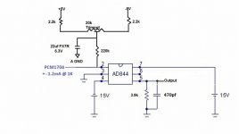
Hmm ... I should add your current source to the sim. It will probably affect the input a little. Any idea where on 20k trim you are (measure)?
Hmm ... I should add your current source to the sim. It will probably affect the input a little. Any idea where on 20k trim you are (measure)?
A touch to the - for the left from middle, and I would say half way between mid and - for the right, as the right dac had about +30mV dc offset and the left about +10mV from memory.
Cheers George
Last edited:
Can anyone say if the output of this buffer (attached) I'm using could handle a muting relay, which shorts to ground for 2 seconds during switch on and switch off.
As the buffer has a 1 volt dc offset on it's output for 1 second during switch off and on, then quickly settles to 1mV
Cheers George
As the buffer has a 1 volt dc offset on it's output for 1 second during switch off and on, then quickly settles to 1mV
Cheers George
Attachments

Last edited:
You can use a double relay, and also short to ground the gates of the jfets, to make sure the maximum gate current that is 10ma is never reach. Or If you use 1k6 in R4 is impossible with + - 15Volts sources to reach the maximum gate current.
You can use a double relay, and also short to ground the gates of the jfets, to make sure the maximum gate current that is 10ma is never reach. Or If you use 1k6 in R4 is impossible with + - 15Volts sources to reach the maximum gate current.
Thanks Sergio, so what your saying as it is, if the output is shorted to ground even for just 2 seconds during switch on or off it will blow the buffers output?
Cheers George
The gate and source (channel) of a jfet forms a pn-junction like a diode , if the voltage at the gate is higher than 0.6 volts this diode start to conduct , the problem is that this junction is week and only withstand 10mA in the case of 2sj103.
If one connect the source to ground , the gate of the Jfet starts to conduct as long the input is higher than 0.6 volts (n Chanel) or lower than -0.6 volts (p Chanel) ,R4 limits the current.
I don't say that in this particular case it will blow the jfet. But is important to understand this potential damage mechanism . I always like to do things safely 🙂
Thanks for that Serg I will get around to it.
But at the moment I have just done some more experimentation with the AD844 and it continues to amaze me.
I just put in a 4.7kohm for the TZ resistor to ground but with just 350pf across it to keep the 1st order roll off similar (around 100khz -3db), and yes on the scope I got a good increase in gain again from what the 3.9kohm gave, hardly any exrta noise, and dc offset still below 1mV, and adjusted out to a stable .1mV
So now I have an abundace of gain at TZ from a 1mA p/p output from the PCM1704. I listened to it and I believe it's as good or even better dynamicly and just as smooth maybe smoother.
How high can one go with the TZ resistor before things start to fall appart sonically and the gain stops increasing?
Because here's a thought, this resistor can become a volume control, if the cap can be eliminated and the filter put down stream on the output buffer, or in front of the I/V. I'm ok as I have a digital domain volume that's being used in the top 1/10 of it's full output range.
Cheers George
Last edited:
George:
I don't recall if the PCM1704 features a muting control input pin. This would be a logic input pin that when asserted sends zeros to the converter, thereby causing the chip to output a bipolar zero analog signal until the pin is un-asserted. You could tie the operation of this logic input to the logic controlling the muting relay. Of course, this would not be an option if the 1704 does not feature such a control input.
I don't recall if the PCM1704 features a muting control input pin. This would be a logic input pin that when asserted sends zeros to the converter, thereby causing the chip to output a bipolar zero analog signal until the pin is un-asserted. You could tie the operation of this logic input to the logic controlling the muting relay. Of course, this would not be an option if the 1704 does not feature such a control input.
Hi Ken the muting circuit is already a part of this cdp on it's analog output rca's and maybe it gets triggered elswhere, I don't have the circuit for it can't even purchase it from Cary CD 303/200. If anyone has it I would dearly love a copy as it is has multi layered circuit board and is a nightmare to track anything.
Cheers George
Cheers George
I have just done some more experimentation with the AD844 and it continues to amaze me.
I just put in a 4.7kohm for the TZ resistor to ground but with just 350pf across it to keep the 1st order roll off similar (around 100khz -3db), and yes on the scope I got a good increase in gain again from what the 3.9kohm gave, hardly any exrta noise, and dc offset still below 1mV, and adjusted out to a stable .1mV
So now I have an abundace of gain at TZ from a 1mA p/p output from the PCM1704. I listened to it and I believe it's as good or even better dynamicly and just as smooth maybe smoother.
How high can one go with the TZ resistor before things start to fall appart sonically and the gain stops increasing?
Because here's a thought, this resistor can become a volume control, if the cap can be eliminated and the filter put down stream on the output buffer, or in front of the I/V. I'm ok as I have a digital domain volume that's being used in the top 1/10 of it's full output range.
Cheers George
I'm ok as I have a digital domain volume that's being used in the top 1/10 of it's full output range.
Cheers George
George, what digital volume control implementation are you using with the PCM1704?

- Home
- Source & Line
- Digital Line Level
- Using the AD844 as an I/V