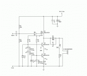
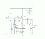
Hi Mirlo. I remember you suggesting that before and I agree that there are benefits to be had. I just don't know if my ears could hear the difference. I've switched to a much simpler regulator that I understand. There were too many negative reactions to the tracking regulator. I'm not saying that the engineers at Linear Technologies are wrong but maybe it isn't the best regulator for audio apps. I will keep your suggestion on paper in the folder that I use for my project and it will probably find it's way into future revisions. Separate onboard regulators for the CCS and Vdd would be a nice touch. Right now the PCB is as crowded as I want it to get. I'm ordering miniboards from Express PCB for the first amp and regulator board and the layout is pretty crowded. The board is only 2.5"x3.5" or so. I'm also thinking about replacing the 1K resistor with a switch contact. It is there to eliminate pops when the headphones are plugged in. This way I get the full benefit of the CCS. Being as this is going to a home headphone amp and not a portable the phones will probably be plugged in all of the time and the switch might not even be necessary much less the resistor. What do you think?
I just realized that the max Vbe of the BJT's in the CCS is 5 volts. I guess that the second led in the Q2 bias will have to go. 🙁
Should be fine, although I wouldn't put in the switch. The 1k resistor is really negligible compared to the 32 Ohm cans. So the high impedance nature of the cascode is not much help in this design, no matter what you do.
There might be a speed advantage from the cascode though, and it is really easy to find out... try it first with no cascode, jumpering from collector to emitter, then put it in, see if you can hear a difference...
By the way, there is no problem with Vbe > 5V even if you use the high voltage blue LEDs, because that is a specification for reverse Vbe, not forward Vbe. The forward Vbe will be something like 0.7 V no matter what, unless you are running too hot, then it will get lower ... leading to thermal runaway. Maybe the 12 Ohm / 3.5 V LED is the best solution.
Caveat: before you select the 3 (or 12) Ohm emitter resistor, _measure_ the voltage drop across the LED with the given current flowing. Select the resistor accordingly. With lower voltage LED and smaller value resistors, the design is more sensitive to small changes in resistance. This thing will run hot, so be sure to heatsink everything well ...
Thanks for the info Mirlo. I guess what your saying is that the advantages of the cascode CCS would be fully utilized in a gain stage where the input impedance of the output stage is much greater than 32 ohms. I'm beginning to understand a little I guess. I will go back with the blue LED's. I'm more comfortable with the higher Vbe. I planned on ordering more than just the 6 LED's and matching them but I will also measure the drop across the LED's as you suggest. I would like to get both channels as close to ideal as possible. The heatsinks that I have are so much more than is needed there is no worry of this little amp ever running"Hot". Thank you very much for your patience with my ignorance and for your help. I will post pics when I have something to show. Right now all I have is a small pile of parts and a lot of ideas. Thanks for helping me tread water when I was in over my head.
Thermal consideration in favor of cascode
Actually, I think the most significant advantage of using the cascode is that it makes the power dissipated in the lower CCS transistor much less, and so lessens thermal runaway issues.
So ignore my idea to try it without the cascode. Sorry I even suggested it.
-- mirlo
Actually, I think the most significant advantage of using the cascode is that it makes the power dissipated in the lower CCS transistor much less, and so lessens thermal runaway issues.
So ignore my idea to try it without the cascode. Sorry I even suggested it.
-- mirlo
I thought that was one of the good things about. It spreads the dissipated power over two devices and therefore is more stable.
I would like to play with transformer coupling this after I get the AC coupled version right. The Sowter 8665 headphone output transformer should give a little more impedance for the CCS to work against and give less distortion on the output. What do you think?
I would like to play with transformer coupling this after I get the AC coupled version right. The Sowter 8665 headphone output transformer should give a little more impedance for the CCS to work against and give less distortion on the output. What do you think?
Transformers!
Well, I have little experience with transformers ... the lowest ratio of the model you mention is 4:1 -- so you will have to swing 4X more voltage. Should still be fine for headphones though -- maybe the correspondingly lower current swing in the follower will reduce its nonlinearity more than the nonlinearity added by the trafo.
I think you still have to capacitively couple it though. I suppose another advantage might be that the output cap is effectively multiplied by the turns ratio.
Good luck,
-- mirlo
The preamp I'm using will put out 10 volts. Granted the "amp" won't swing 10 volts but power is power. I think that the distortion of the transformer will be less than the distortion of the electrolytic cap on the output. Even an Elna Cerafine. Plus the CCS will work better. Hey if McIntosh can do it ....................... Talk to you later.
I think you have to be careful with running the trafo DC coupled. The information on Sowter's website suggests it is to be AC coupled, and the other ones designed for SE triode amps don't like as much DC current as you have in this design.
http://www.sowter.co.uk/acatalog/SOWTER_TRANSFORMERS_HEADPHONE_TRANSFORMERS_28.html
http://www.sowter.co.uk/acatalog/SOWTER_TRANSFORMERS_HEADPHONE_TRANSFORMERS_28.html
I'm not going to try to DC couple it. Using the transformer allows me to use a much smaller film cap though. Which I think might be preferable. I'm going to try the original design first and go from there. It may sound so good that I won't mess with it any more. We'll see. Have a good one Mirlo.
Hi Troels,
I went to the Welborne labs site and downloaded the diagram of their PS1 power supply and just took the positive half of the diagram and layed out a pcb for it. I haven't had the board made as I have gotten distracted(again) and am currently working on putting together a ZEN V4 amp. I have the pcb layed out for both regulators(using ExpressPCB) if you would like me to send them to you. There was some question as to how effective the tracking regulator would have been and the circuit is a little over my head so I can't give you opinions on how well it will work.
G
- Status
- Not open for further replies.
- Home
- Amplifiers
- Solid State
- Using Back To Back LT1085s

