RC filters
The resistors are small value, high wattage types. Probably metal film or metal oxide.
Even if I can't seem to find the original Ben Duncan supply, on The Audio Amateur implementation, they did the same as Duncan.
On TAA's supply series resistors are four 1 ohm, 2W types, followed by 2,000uF. Then another 1 ohm/2W followed also by 2,000uF.
So drop should be nil almost.
Carlos E. Martinez
Agreed, this is far more acceptable than the original resistor that was in place.  Worth having there.
 Worth having there.
33 ohm series resistor seriously limits the current output.
Yep...... a few volts into a 10K load is some current output alright.....
Yep...... a few volts into a 10K load is some current output alright.....
HH,
I dont recall seeing anywere here that G only wanted a few mA output.... If this is the case, the 33ohm resistor is fine obviously but I didnt see evidence that this supply was strictly intended for very low current output.
I dont recall seeing anywere here that G only wanted a few mA output.... If this is the case, the 33ohm resistor is fine obviously but I didnt see evidence that this supply was strictly intended for very low current output.
Final Design
Hello All,
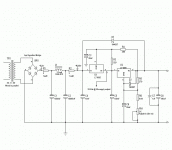
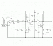
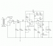
This is the last design as far as I can tell. I read and reread the datasheet on the LT1085 and made adjustments accordingly. As long as the Formula is correct(Vout = Vout(R2/R1)Iadj x R2) then the calculations should be correct. Maybe this isn't the optimal implementation of this type of regulator circuit but I think that the performance should be very good. Since I am only looking for 300mA it should more than suffice. All of the capacitor values after the CLC filter are made according to the values found in the datasheet with the exception of C7. I put it there just to make myself feel better😀.
Thanks for all of the help. Especially AudioFreak and ALW. If anyone would like I have a board layed out for the regulator using ExpressPCB. Not the greatest layout software but it serves my modest needs. Just drop me an email and I will send it right off as soon as I can. Thanks again guys.
Attachments
Regulators
The data sheets show the specifications graphed at Vin_Vout >3 volts. You are degrading the performance of the reglator by operating at less than this voltage across it. Split the voltage drop equally across each regulator to get the same power dissapation across each and you won't need to heatsink one them. The 3 ohm resistor will allow a voltage of three times the change in load current to appear at input of the first regulator, degrading the circuits PSRR as afunction of change in load current. Leave it out since you are already using a LC filter at its input. Replace the 200 ohm resistor across the adjustment terminal with a 1K ohm for an adjustment current of 1.25mA and the 300 ohm resistor with two series connected green LEDs this will give better regulation and about 4.85(1.8x2 for the LEDs plus 1.25) volts across the second regulator. Add a 0.1 film cap from Vin to ground for the first regulator. These changes are worth making.
Art
Regulator change
No, you have the 1K resistor and the LEDs swapped. I swapped resistor values in my description trying to post from my memory of your circuit. Make sure the LED are the correct polarity also. You don't "have" to change anything if you don't think it is worth the trouble, I just though you wanted the best simple circuit with two regulators. Red LEDs have a lower foward voltage than green by the way. Also put a protection diode from Vout the Vin for the first regulator to discharge the 150uF output cap when the circuit is powered down.
Art
G,
artnyos has some good points, also let me again warn you... I see in your latest schematic that you have again added the 150uF output cap with 1uF bypass. Low Drop-Out regulators are extremely picky about the output cap as it is used to ensure stability. A 10uF solid tantalum capacitor is by far your safest choice here.
artnyos has some good points, also let me again warn you... I see in your latest schematic that you have again added the 150uF output cap with 1uF bypass. Low Drop-Out regulators are extremely picky about the output cap as it is used to ensure stability. A 10uF solid tantalum capacitor is by far your safest choice here.
Reading the Data sheet.......
A 150uF low ESR type should be fine. Try a Panasonic FC series electrolytic. I may breadboard this weekend if I have time, but I have used the LT reglulators with electrolytics with no problems in the past. Tantulums don't sound good for audio.
From the data sheet:
Stability
The circuit design used in the LT1083 family requires the use of an output capacitor as part of the device frequency compensation. For all operating conditions, the addition of the output will ensure stability. Normally, capacitors much smaller than this can be used with the LT1083. Many different types of capacitors with widely varying characteristics are available. These capacitors differ in capacitor tolerance (sometimes ranging up to ±100%), equivalent series resistance, and capacitance temperature coefficient. The 150mF or 22mF values given will ensure stability. When the adjustment terminal is bypassed to improve the ripple rejection, the requirement for an output capacitor increases. The value of 22mF tantalum or 150mF aluminum covers all cases of bypassing the adjustment terminal.
Without bypassing the adjustment terminal, smaller capacitors
can be used with equally good results and the table below shows approximately what size capacitors are
needed to ensure stability.
Art
Art,
If I remember correctly, we want an ESR of 2-8ohms and a stable capacitance into the MHz range. I'd take the 10uF solid tantalum.
If I remember correctly, we want an ESR of 2-8ohms and a stable capacitance into the MHz range. I'd take the 10uF solid tantalum.
I'd take the 10uF solid tantalum
And I would not. If Linear technologies says an 150 uF electrolytic works fine I guess they would know. The FC series have very low ESR as do any number of electrolytic caps designed for switching power supplies. the whole electronics industry is moving away from tantalums. Some of the orgamic semiconductor caps have ESRs lower than many tantalums and also sound very good. By the way its milliohm levels we are talking about not ohms For ESR! Read the data sheet and stop shooting from the hip. Tantalums sound bad, are more expensive and very unforgiving of overvoltages and shorts. I have seen them bounce off the ceiling when they explode. Still want to argue about capacitors with me?
Art
I wish not to argue but I will state that I did indeed mean ohms and I was reading for a data sheet on LDO's. The LDO that we are using here appears ok with the 150uF electrolytic on output with 20uF on the adjust pin. 

Easy guys. You both obviously know far more about electronics than I do. Look at this as a group effort. I have never heard anything good about using Tants in any circuit that has anything to do with audio. Which means absolutely nothing because I'm sure that haven't heard everything(gasp!). I just prefer to use electrolytics. I like the idea of using LED's to bias the pre reg. It should eliminate thermal drift. I had already planned on using Pana FC's in the PSU and in the amp as well. Every part that I plan on using is in the Digi-Key catalog. When I finally get the whole thing together(schematics, parts lists, etc.) I'll post them here and a few other places as well. Everyone that has helped will be acknowledged in the article that I plan on submitting to the Headwize Library. I really haven't designed anything. I merely acted as a catalyst. Gabe Velez designed the circuit that started this whole project of mine. I just wanted a really good supply to go with the circuit. Hopefully it's getting close to final now. Thank you everyone. I've learned a lot from all of you.
Attachments
G,
It looks to me as though you have the polarity of D2, D3 and D5 reversed relative to how they should be.
It looks to me as though you have the polarity of D2, D3 and D5 reversed relative to how they should be.
D2 and D3 should have their anodes torwards the highest voltage otherwise they won't conduct. D5 is there to discharge C6 when the power is turned off. I think that both C6 and C7 will discharge through the R3, R4 and RV1 bias network when the power is turned off. At least thats what I thought I was doing. But wait. Ah, I see it now. D5 IS reversed. Thanks. But I still think that the LED's should be right. I will have higher voltage on the anodes as compared to the cathode due to the voltage drop across R2 won't I? How confusing. Wait a minute. As it is now D5 will short around the R2,D2&D3 bias network, rendering it useless(and probably destroying the regulator also). I wonder how I'm going to discharge C6 when I turn off the PSU? Let me work on this for a while. Thanks AF.
The LED's are reversed. Higher voltage is present at the input of the the 2nd regulator than is present at the output of the same regulator so current flows toward the output.
- Status
- Not open for further replies.
- Home
- Amplifiers
- Solid State
- Using Back To Back LT1085s


