If I reverse the values of R2 and R3 in the equation then I get a Vout if 1.43 volts. Is this what you are saying ALW?
G,
For your diagram,
V(pre reg)=1.25(1+(R3/R2))
Set this for about 1.5V
It's floating so the voltage from the pre reg will be final output + V(pre reg).
For your diagram,
V(pre reg)=1.25(1+(R3/R2))
Set this for about 1.5V
It's floating so the voltage from the pre reg will be final output + V(pre reg).
Hi AF. I'm more than just a little confused. I've reversed the values of R3 and R2. Then I changed the value of 287 ithink it was to 499 and using the formula given in the spec sheet:
Vout=Rref(1+(499/4990))+.00005x499
Vout=1.68 volts
I then changed R4 to 249 Ohms and using the formula :
Vout=Rref(1+(4990/249))+.00005x4990
Vout=28.79 volts
Which gives me a total Vout of 30.47 at the junction of R3 and R4.
Is this correct?
Vout=Rref(1+(499/4990))+.00005x499
Vout=1.68 volts
I then changed R4 to 249 Ohms and using the formula :
Vout=Rref(1+(4990/249))+.00005x4990
Vout=28.79 volts
Which gives me a total Vout of 30.47 at the junction of R3 and R4.
Is this correct?
High value cap at output
I have read some reports that you shouldn't use a high value cap after regulators like 3X7s or those LTs. You should never exceed 150uF or so. Penalty seemed to be oscillation.
What really seems to do the trick is hanging a large cap from the adjusting leg to ground in parallel with the resistor. You should bypass it with a protection diode anyway, as you from output to input.
Carlos
The problem with large caps on the output is that ESR becomes too low and sure enough oscillation is the result
G,
Set the output regulator for 30V.
Set the Pre-Regulator for 1.5V.
Given that the formula is:
V=1.25*(1+(R2/R1)) + 0.00005*R2
R1 is always the resistor that leaves Vout from a given regulator and meets with the Adjust pin of the same regulator. R2 is the resistor that joins with R1 at the Adjust pin.
Calculate the values of each regulator independent of the other.
If you follow the instructions above, the pre reg will output 31.5V and the output regulator will output 30V. This means that a constant 1.5V is dropped across the output regulator.
Hi AF,
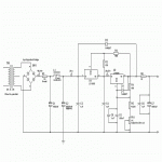
According to page 9 in the spec sheet for the LT1085 R2 is the resistor connected from the Adj pin to ground and R1 is the resistor connected from Vout to the Adj pin. Now don't get me wrong. I'm certainly not arguing with you or anything like that. It's just that I want to make sure that I have this straight before I lay out a board for the circuit. Also I added a 10 ohm resistor on the output of the PSU to take care of any oscillation due to the low esr of a larger capacitor. I planned on using Panasonic FC caps for everything except the 15KuF caps which will be Panasonic AA's. Think the resistor will do it? It's only going to drop 3v which I can easily adjust out with the pot. R3 is 499 and R4 is 196. I had to reduce the size of the Gif so it's a little difficult to read. BTW I adjusted the pre reg to put out 30.5v + 6.07v and the regulator to put out 33.32v to allow for the voltage drop across R6.
According to page 9 in the spec sheet for the LT1085 R2 is the resistor connected from the Adj pin to ground and R1 is the resistor connected from Vout to the Adj pin. Now don't get me wrong. I'm certainly not arguing with you or anything like that. It's just that I want to make sure that I have this straight before I lay out a board for the circuit. Also I added a 10 ohm resistor on the output of the PSU to take care of any oscillation due to the low esr of a larger capacitor. I planned on using Panasonic FC caps for everything except the 15KuF caps which will be Panasonic AA's. Think the resistor will do it? It's only going to drop 3v which I can easily adjust out with the pot. R3 is 499 and R4 is 196. I had to reduce the size of the Gif so it's a little difficult to read. BTW I adjusted the pre reg to put out 30.5v + 6.07v and the regulator to put out 33.32v to allow for the voltage drop across R6.
Attachments
G,
Fixed the R1/R2 problem... suggest you read my last post again now.
That 10ohm resistor will hurt the regulation as the voltage drop across the resistor is dependent on the current flowing thru it. I'd tend to replace the 1000uF output capacitor with a 10uF tantalum capacitor and omit the 10ohm resistor completely.
You only want 1.5V across the output regulator so change R2=620ohms and R3=120ohms
Then change R4=270, R5=5.6k and VR1=1k for 30V on the output.
Hi AF,
I will make the changes that you indicated. I do have one question. On the amplifier board(which will be in a separate case) I have a 1000uF cap and a 470uF cap mounted on the Vs line. These capacitors will have about 24 inches of cable connecting them to the PSU via an umbibical cord. Is this acceptable as fas as regulator stabibility goes? Also, why Tantilum caps? I'm just curiuos. Do they have a certain property that I should know about? Thanks very much for your help. I plan on taking the PSU diagram to school and have the teacher go over it with me so that I understand exactly how the tracking regulator works. I will post the new diagram for everybody that maybe needs a PSU like this. Thanks again.
G
G,
Why Tantalum?
Because a tantalum capacitor of around 10uF has just about the right ESR for the job. If the ESR is to low or too high you run into stability / regulation problems. This is also primarily why these regulators do not like large output capacitors. Also you must look at how the capacitance holds up at high frequency. If the capacitance drops too low at high frequencies, you get instability. Tanalum just fits the job well all round in this case.
The off board 1000uF + 470uF filter caps should not cause problems as they will be decoupled from the regulator by the series resistance of the cable between them and the regulator.
Hi AF,
Isn't 1.5 volts across the regulator cutting it a little close to the dropout voltage of the regulator. I will be mounting these regulators on a good sized heatsink so over heating won't be a problem. If 1.5 volts won't be a problem then 1.5volts it is. Thanks for the explaination on the Tant caps. That's good to know.
G
Also, R1 should be omitted as it will limit the current that can be drawn before the regulation drops out due to excessive voltage drop across R1.
1.5V for the pre reg should be fine.
1.5V for the pre reg should be fine.

One last thing. Now that we have that sorted out, you might want to use a lower voltage transformer perhaps 30V.
Series resistors
I'm not so sure if it's not not better to leave those series resistors, used as part of an RC filter.
Some years ago Ben Duncan used two RC filters, one after the other, on the raw supply of a large hi-quality pramp project in Hi-Fi News and Record Review. The idea was to feed a garbage noise voltage to the regulator.
A similar RC was also implemented on a recent microphone preamp project on Audio Electronics, before a Sulzer supply.
Carlos
feed a garbage noise voltage
I believe you mean" feed a garbage FREE noise voltage". RC filters are a great idea.
H.H.
I believe you mean" feed a garbage FREE noise voltage". RC filters are a great idea.
H.H.
Garbage
Of course I meant garbage free. I just had made a different word arrangement and lost one in the middle.
Sorry!
Carlos
Of course I meant garbage free. I just had made a different word arrangement and lost one in the middle.
Sorry!
Carlos
I certainly see your point but a 33 ohm series resistor seriously limits the current output. You'd have to go quite a bit lower before I'd leave it in 🙂
- Status
- Not open for further replies.
- Home
- Amplifiers
- Solid State
- Using Back To Back LT1085s