Several years ago, when I was still living at an apartment I was dropping off some trash and found someone was throwing out a nice analog 42W Weller soldering station and an Elenco 1525 35Mhz Oscilloscope, both of which I promptly grabbed. I love the soldering station, I use it all the time. But as far as the scope is concerned, I never used it and I confess, I have no idea how. I very familiar with using a traditional DMM, I use them all the time at work, but never an oscilloscope.
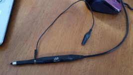
I have no idea how to use this thing, I'm familiar with a DMM having two leads, but this thing only came with one connected to the Yaxis input. Though I see that this lead has secondary to the probe tip, there is a separate collar connect to short removable lead with an alligator clip, with a three position switch on the side of the probe (1X, REF, 10X).
Would I be correct in assuming that is I wanted to look at the output of a 12vac power supply, would I connect the alligator clip to one side of the power of the output and touch the probe tip to the other? Or am I an the complete wrong track and I would be creating a direct short across the output?
Here is the scope and probe in question. Thanks for any help in advance.
Attachments

Google for oscilloscope basics,,there are some good introductions and also some videos on YouTube. This is the most useful bit to test equipment you can have in my opinion and is well worth getting to know.
The scope you have there is a two channel one and good enough for audio at a minimum,Try the makers ( Elenco ) for a manual, This would be very useful to identify and set the controls.
Note with a scope the Chassis is earthed and the croc clip on the probe is connected to the chassis - this goes to the ground on the equipment being tested. The probe itself is used to measure against ground.
alan
Note with a scope the Chassis is earthed and the croc clip on the probe is connected to the chassis - this goes to the ground on the equipment being tested. The probe itself is used to measure against ground.
alan
So to look at the output of a transformer as mentioned above, one leg would need to be grounded so otherwise there would be no potential to measure? I'm already searching through the Elenco website.
provided the output winding is not connected to ground you can connect the ground and probe to either terminal. The ground is provided by the scope.
The problem comes if the transformer already has one winding grounded or is rectified and a ground is attached to one of the DC outputs then the scope ground needs to be attached to the transformer ground.
The problem comes if the transformer already has one winding grounded or is rectified and a ground is attached to one of the DC outputs then the scope ground needs to be attached to the transformer ground.
Makes sense. I suppose in that case I can test each leg of the transformer with out grounding it, and if there is any potential to either leg I would know it was grounded.
One other question, is that do I need to select a voltage range like older multimeters? Start higher and work my way down? I'm just trying to figure out what range i can safely work on with this scope.
Thank your for your help, I'll try and find a manual for this thing before I ask any more questions unless I just don't understand something.
the scope has a control marked in volts/div (ision) for each chanel
Start high at 10V division that would be 40v - 0 - 40v, on the screen 4 division either side of the centre (0) line.
the probe will probably have a x1 and x10 switch - the 1 is as the control states ie 10v per division, the x10 would change the reading to 100volts / division (10 times the scale). Put the probe on x10 then you could measure +_ 400 V peak to peak.
Now measure then adjust so the measurement fits on screen nicely.
the Chanel has AC ground and DC switch. With the scope in Auto mode so it self triggers and the switch on Ground,you will have a line across the screen, this is at 0Volts, adjust the position so the line is in the middle.
Set to AC or DC to measure the signal. AC puts a small capacitor in line with the signal.
Use the time base to spread out the signal to see the waveform.
Hope this helps
alan
By far my favorite oscilloscope training video:
It is LONG as hell but takes you from knowing nothing to REALLY knowing how to use your oscilloscope.
NJARC Oscilloscope School a.k.a. "Scopes For Dopes" - YouTube
Table of Contents:
0:00:00 Opening and Agenda
0:02:50 Brief History of Oscilloscopes – with Al Klase
0:15:00 Start of Basics of Oscilloscopes – with Alan Wolke
0:19:00 Basic Block Diagram of an Oscilloscope
0:19:50 Oscilloscope / Display Overview
0:23:00 Display Section Functions and Controls
0:28:10 Vertical Section Description
0:33:17 Vertical Scale / Coupling Controls, Input Impedance
0:38:04 Vertical Mode Controls
0:48:05 In-circuit Example of using two traces on the oscilloscope
0:52:41 Horizontal Section Description
0:53:48 Horizontal Sweep Types & Controls
1:10:15 Triggering (Synchronization) Section Description
1:13:19 Trigger Source, Mode and Coupling Controls
1:19:56 Trigger Level and Slope Controls
1:23:29 Introduction to Oscilloscope Probes
1:31:45 1X and 10X Passive Probes
1:34:00 10X Probe Compensation and Use Considerations
1:48:48 XY Mode of Operation
2:00:12 Front Panel Control Layout
2:02:20 Pop Quiz!
2:03:00 Wrap Up: Oscilloscope adds Intuitive Feel to circuit operation
2:04:45 Questions and Answers
2:13:35 Brief History of Oscilloscope Tubes
Also this guy has a variety of good videos on his youtube channel.
The scope is really just a visual voltmeter.
Its more than that, its a 2D machine. Handles value in time.
So I'm thinking my scope my be broken, this is what I get when I try the onboard .5v peak to peak square wave generator. What is the possibility that the onboard test function has failed and it's not the function of the scope? Is there another good way to test out a scope?
Attachments
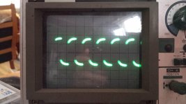
There is no problem whatsoever, you just need to adjust the probe in x10 setting. If you have a closer look, you must see a slot on the probe body, that you can adjust with a screwdriver until the top of the waveform is flat.So I'm thinking my scope my be broken, this is what I get when I try the onboard .5v peak to peak square wave generator. What is the possibility that the onboard test function has failed and it's not the function of the scope? Is there another good way to test out a scope?
These are short but very useful tutorials:
What is an Oscilloscope? Oscilloscope tutorials for beginners | Electronics tutorial videos
What is an Oscilloscope? Oscilloscope tutorials for beginners | Electronics tutorial videos
There is no problem whatsoever, you just need to adjust the probe in x10 setting. If you have a closer look, you must see a slot on the probe body, that you can adjust with a screwdriver until the top of the waveform is flat.
I guess I need to finish watching that scopes for dopes video, I'm only about half way through. I apparently didn't make it up to probe calibration section. Thank you your help that worked perfectly.
An oversimplication, an oscilloscope is a plotter with a sophisticated triggering system, without which its almost unusable (and understanding how to setup triggering will is very important). Most 'scopes these days do spectral analysis too and automate many signal measurements and statistics. More a Swiss-army knife I reckon - there's always some option you've never found a use for!
- Home
- Design & Build
- Equipment & Tools
- Using an Osccilloscope...