My point was that when theory and reality conflict, the theory gets altered.
Unless you are an economist ...
FWIW, the best sounding amp I've built is all sand. But, it is transformer coupled on the input (Lundahl amorphous) and the output (Cinemag nickel) and the circuit is basically a "tube" circuit except I can get away with 150 ohm OPTs. I generally prefer tubes to sand, but really what I prefer are good designs. 🙂
That, right there, is a major departure from the design of every Big Box SS amp. No OPT is cheaper than the cheapest OPT. As for SS designs, if I can ever get ahold of these new SiC JFETs, that's what I'm going to do.
SS amps don't have to sound as horrible as they do. A BJT based design can sound surprisingly good, if you do the design right.
I've yet to hear one, but my business partner ranks Gary Pimm's SS Tabor as one of the very best amplifiers he has ever heard.
It uses transformers in and out and a HV B+
dave
It uses transformers in and out and a HV B+
An externally hosted image should be here but it was not working when we last tested it.
dave
My point was that when theory and reality conflict, the theory gets altered. The Michaelson/Morely experiment and Einstein's Special Relativity are a paradigm case.
Thus it is with all things science. First comes the theory then comes the experiment. I believe that Einstein's theory of special relativity failed the first time it was tested. Of course the measurement was flawed...
Point understood. I just have a pet peeve with that particular point. I think it to be interesting that those kind of observations continue on far after they are no longer valid. I suppose because it is more interesting than the alternative.
Since I have nothing of any use to share, here, I will leave this topic in peace.
Aerodynamic theory says a Bumble Bee can't fly. 😀 The H/K Cit. 2 employs approx. 36 dB. of NFB in 3 nested loops. The design is unconditionally stable. Like aerodynamic theory, chaos theory must yield to empirical reality.
BTW, the "Duece" sounds VERY good.
Uh, FWIW, the aerodynamic guys figured out that they were using the wrong Reynolds number for the bumble bee thing, about 20 years ago. IOW, now they have the math that shows that it *does* fly.
Regarding amplifiers and stable behavior (this will be easier to follow along if you have some Chaos background, see 'Chaos' by James Gleick as a very nice primer or see Chaos_theory): If you apply feedback to an amplifier, the only way to get stable behavior is to apply *positive* feedback. This causes the amp to oscillate. When oscillating, the amplifier condition is stable, that is to say it will not change until you unplug it. It is also stable when it is off.
Negative feedback produces instability as it produces bifurcation of the input signal. The bifurcation will be in multiples of 2 and 3 and harmonics up the 85th and beyond will be seen, although obviously some harmonics will be so high that even though the amp makes them, it cannot amplify them. There will also be distortions that are in-harmonically related to the input, due to intermodulation at the feedback node.
So far this should not be that mysterious- Norman Crowhurst wrote about this in the 1950s. However, if you know Chaos Theory, you see that the behaviour described is that of an unstable system- one that has a stable behavior within certain conditions. Another example of that is a Lorenz Water wheel- Goodle that and you will find plenty of references.
(Examine the noise floor of an amplifier without feedback and you will see that it is the same thing as noise out-of-doors. Different subject in a way, but you will easily see its not coincidence- the two systems have the same noise floor curves due to similar behaviors.)
Anyway, back to distortion. It **is** a common belief amongst many designers that feedback is a stabilizing factor in amplifier design. However you will note that many amplifiers require networks in the feedback loop to accomplish that- certain frequencies are not allowed. The reason this is a problem is that there is a time delay in any amplifier circuit called propagation delay. So when the feedback arrives back at the input it is too late to do the correction it is supposed to. With sine waves its not such a big deal- the amp can lock in on the signal after a few iterations. This is one of the stable modes of the unstable dynamic system.
With a changing waveform its another matter. Imagine for a moment a positive going pulse of time t and the amplifier circuit of time t+1. The idea here is to understand that the pulse and propogation delays are very close to each other. The output of the amp will have the pulse, which is feed to the input, but the pulse no longer exists. A negative-going pulse will appear at the output (of lower amplitude), which is fed back once again and so on. IOW, the amplifier output *rings*. To limit this behavior, networks are installed in the feedback loop; this can be a tricky process otherwise your circuit can go into oscillation or have other undesirable effect.
Every designer knows this. So- where in this is there seen the quality that feedback creates stability? The very fact that you have to design around it tells you that such is not the case. The only example of true stability is a zero feedback circuit.
There is a great example of IBM and Cantor dust that points to this phenomena, and I also refer you to Nelson Pass' article about Audio, Distortion and Feedback wherein we see that you just can't seem to get rid of those pesky odd orders just by adding more feedback. Chaos Theory is telling us, IOW, that we are not going to win the battle against distortion by going brute force with feedback, any more than IBM was going to win against bit errors by increasing signal strength (which is why they invented the parity bit).
Last edited:
That is only a small part of the reason. A good triode is still the most linear amplification device invented by man.
dave
Thanks for that Dave, it took me a minute to work out what was going on but I won't make that mistake again. 🙂
Everyone else - thanks for the huge amount of info! I'm definitely keen on valve amps now though it'll take me a while to work through all of the information in these posts I think.
Five minutes with a tube amp and an oscilloscope will convince you that this is not true.
But I take it that a big part of the sound difference (apart from the other reasons - impedance spectrum of the speakers etc.) is the lack of higher-order harmonics in the overload-induced distortion. If this is still true then where does this property come from?
If this is still true then where does this property come from?Five minutes with a tube amp and an oscilloscope will convince you that this is not true.
It is true. Five minutes with a tube amp and an oscilloscope will convince you that this is so. Not sure what SY was getting at, but if you clip a valve amp you will (nearly) always get a softer transition into the clip than a transistor amp will give. In other words, the edges will be rounded off where an SS amp gives sharp edges. NFB may make the clipping harder, but as far as 'fair' comparisons are possible, valve amps clip softer.
Not sure what SY was getting at, but if you clip a valve amp you will (nearly) always get a softer transition into the clip than a transistor amp will give.
When a push-pull tube amp clips, it clips just as hard and just as symmetrically. The transitions are sharp and full of higher order harmonics. I'd post a scope picture, but I'm 1500 miles from home at the moment...
Now it IS true that single ended circuits can be designed to have their even order distortion rise faster than odd order (non-symmetrical). However, this is not specific to tubes- you can see the same effect in single ended solid state amps.
RK, I have a fair background in nonlinear dynamics (used to hang out with Yorke when I was an undergrad at UM in the mid '70s, his sister was my physics advisor), so it's not out of total ignorance that I have to admit that I can't make any sense out of what you're saying. BTW, Gleick's book is entertaining and a nice book for people who don't want to see any math, but it's not a great primer into the subject so much as it's a well-told story about the excitement and importance of the subject. Ian Stewart's "Does God Play Dice" is (IMO) a better intro for people with some technical background. Engineers might want to go directly to Ott's "Chaos in Dynamical Systems."
In any case... let's talk about those compensation capacitors. Admittedly, I'm not an engineer and have no engineering training. But looking at the actual propagation delays of amplifiers (order of magnitude ~2-3ns) and the time constants of the compensation (order of magnitude ~10us), I'm having trouble believing that one relates to the other. And since Nyquist and Bode do an excellent job of predicting amplifier behavior with feedback without resorting to nonlinear dynamics, I'm having trouble seeing that relationship, too. The concept of "feedback being applied after the fact" has been thoroughly debunked elsewhere, so I won't open that can of worms.
In any case... let's talk about those compensation capacitors. Admittedly, I'm not an engineer and have no engineering training. But looking at the actual propagation delays of amplifiers (order of magnitude ~2-3ns) and the time constants of the compensation (order of magnitude ~10us), I'm having trouble believing that one relates to the other. And since Nyquist and Bode do an excellent job of predicting amplifier behavior with feedback without resorting to nonlinear dynamics, I'm having trouble seeing that relationship, too. The concept of "feedback being applied after the fact" has been thoroughly debunked elsewhere, so I won't open that can of worms.
Solid state is unavoidable if you listen to digital, I have yet to hear a tube DAC that competes with a good zerofeedback SS analog stage. Thats one area tubes have failed us.
Thus it is with all things science. First comes the theory then comes the experiment.
Somewhat OT, but this is a common misconception. First comes observation. Then comes hypothesis (we'll skip over conjecture for brevity's sake), which must be consistent with all observed phenomenon. Then the hypothesis is tested against predicted outcomes and continued observation. When inconsistencies are observed or predicted outcomes not found, the hypothesis is modified or replaced. Only when this has been done over an extended period of time and test does the hypothesis become theory.
Sheldon
Inductive versus deductive reasoning ? Both have been used in science in the past so you are both wrong. Happy ? 😀
Solid state is unavoidable if you listen to digital, I have yet to hear a tube DAC that competes with a good zerofeedback SS analog stage. Thats one area tubes have failed us.
It's not the tubes that have failed us, it's the fashion-driven designers.
It's not the tubes that have failed us, it's the fashion-driven designers.
Show me a tube output stage for an i-out DAC that has an input imedance under 5. I'll build it and be the first to eat my words.
BTW its tubes only for preamps and amps for me.
We just haven't unlocked the secret for the analog section of decent (i.e. R-R) DAC's. I've come close with passive/IV+ high gain tube but still miss the low level detail and dynamics that a good zero feedback SS design provides.
Show me a tube output stage for an i-out DAC that has an input imedance under 5. I'll build it and be the first to eat my words.
I think it could be done. I'm not sure you need 5R, at least for most I-out DACs, but it is certainly designable. For example, a TDA1541 swings 2 ma. Across a 5R, that's 10mV, well within the range of a quiet phono amp-style stage, especially if you use a 1:10 step-up transformer. With a tube like a D3a, with equivalent noise resistance of 60R or so, the signal to noise with a stepup could be superb.
If you wanted to get fancy with the topology, a high gm/high mu triode with plate to grid feedback could make a summing junction with a VERY low impedance.
Sorry, I have little experience with DACs and such. What do zero-feedback solid state I/V converters look like?
To me, the most obvious way to do active I/V conversion would be with feedback. I don't see how to do it without feedback unless I/V conversion is passive and you are just amplifying the voltage from there. I'd love to learn a new trick.
To me, the most obvious way to do active I/V conversion would be with feedback. I don't see how to do it without feedback unless I/V conversion is passive and you are just amplifying the voltage from there. I'd love to learn a new trick.
Inductive versus deductive reasoning
But both derive new theory from existing theory, and so still need to be verified against what be observe... 🙂
I think you should definitly post the scope shots when you get home, if you get the chance, because I've yet to see any PP amp that clips as hard as an SS! (Although I have not yet played with a high-feedback amp with dubious stability, which might do what you describe, hmm...)When a push-pull tube amp clips, it clips just as hard and just as symmetrically.
My amp (currently, the Red Light District, with a Pete Millett Engineer's Amp on the side) is quite stable and has very moderate amounts of feedback. In fact, the RLD was specifically designed to minimize overload recovery issues.
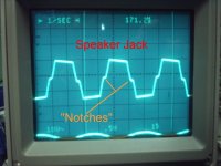
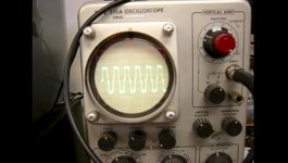
These (attachments) are from guitar amps that are usually designed for more softer clipping at expense of THD figures. The first is a tweed Fender, second a Satellite "boutique" amp. Still... rather hard clipping.
Few more...
Push-pull 2A3 amp, medium overdrive:

SS devices, extensive overdrive:
Few more...
Push-pull 2A3 amp, medium overdrive:
SS devices, extensive overdrive:
An externally hosted image should be here but it was not working when we last tested it.
Attachments
Last edited:
- Status
- Not open for further replies.
- Home
- Amplifiers
- Tubes / Valves
- Usefullness of tubes