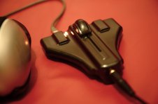
Having considered purchasing a USB DAC and headphone amplifier for my system I found that I couldn't quite find a product which met all my requirements. Then about 1 year ago I was inspired by a National Semiconductor chipset (as have a few diyers on this forum) to build a small desktop DAC and headphone amplifier to meet my own specification. The sound quality was so good that I took the design from basic prototype through to proof of concept and even got to grips with 3D CAD software to design the plastic enclosure. The results of which I have attached to this thread.
You can see more pictures here
Headphone Amplifier - a set on Flickr
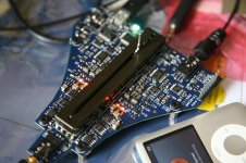
Functionally the unit is powered by the USB 5V supply from which I generate a split rail using DC Converters. I then clean up the analog power with a Super Regulator (thanks to Walt Jung). USB audio is handled by a TI PCM2906 which outputs to a Wolfson WM8804 SPDIF transceiver with jitter attenuation. The DAC is a low power Wolfson WM8718 device. The product also has a mini optical toslink input with analog audio option and system management is handled by a programmable logic device (Lattice). The analog amplifier section uses TI LME49720 op-amps coupled to BUF634 unity gain high speed buffer. Power supply decoupling is handled by Wima SMD capacitors and some higher capacity Nichicon KA and FG series components.
I made a handful of units which I've shared with family and friends and I thought I would now post to the DIY Community. Thanks to Steve Soibelman for pointing me in this direction.
I call this Project Jaina.
You can see more pictures here
Headphone Amplifier - a set on Flickr
Functionally the unit is powered by the USB 5V supply from which I generate a split rail using DC Converters. I then clean up the analog power with a Super Regulator (thanks to Walt Jung). USB audio is handled by a TI PCM2906 which outputs to a Wolfson WM8804 SPDIF transceiver with jitter attenuation. The DAC is a low power Wolfson WM8718 device. The product also has a mini optical toslink input with analog audio option and system management is handled by a programmable logic device (Lattice). The analog amplifier section uses TI LME49720 op-amps coupled to BUF634 unity gain high speed buffer. Power supply decoupling is handled by Wima SMD capacitors and some higher capacity Nichicon KA and FG series components.
I made a handful of units which I've shared with family and friends and I thought I would now post to the DIY Community. Thanks to Steve Soibelman for pointing me in this direction.
I call this Project Jaina.
Attachments
Mach 1 🙂
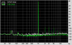
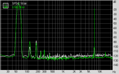
Sounds great! I haven't been able to test with an Audio Precision or Dscope yet but using my sound card and RMAA I get encouraging results.
Sounds great! I haven't been able to test with an Audio Precision or Dscope yet but using my sound card and RMAA I get encouraging results.
RMAA results attached.
I think I am seeing the limitations of the sound card used to capture this analysis rather than the USB DACs true performance. Only an audio tester can resolve this to better precision
I think I am seeing the limitations of the sound card used to capture this analysis rather than the USB DACs true performance. Only an audio tester can resolve this to better precision
Attachments
nice work!, hey did you give one to Steve? I've been (more than) a bit slack sending him some (gifted as I wont build them) O2 headphone amp PCBs for him to build with his daughter. Hes helping me with a baffle design for a set of DIY speakers.
you must be boosting the voltage a fair bit with those DC-DC convertors, the superegs are not exactly low dropout and the buf634 not exactly efficient. well done, may I ask specifically which boost convertor?
you must be boosting the voltage a fair bit with those DC-DC convertors, the superegs are not exactly low dropout and the buf634 not exactly efficient. well done, may I ask specifically which boost convertor?
Last edited:
Cheers qusp! I just connected with Steve on a LinkedIn discussion on the Audiophile Forum regarding this project and he suggested I open this design up to the diyaudio community. So no he doesn't have my product...yet. He did mentioned he's actively involved in speaker design which is interesting. DIY speakers are great fun, I had a go about 15 years as a joint project with a friend using some Lowther drivers and their Fidelio cabinet design.
Regarding the DCDC converters on Jaina, I'm using:
LMR64010 Step Up Boost Converter to provide +6.4V
LM2611 Cuk Converter to generate -6.4V
I then regulate to plus/minus 5.75V using off the shelf LDOs (LT1963 & LT3015).
The Super Regulator has a dropout of ~1V so I added a bit of margin and run the clean analog supplies at plus/minus 4.50V
I could maybe run the amps with a slightly higher voltage and just stay within the 500mA USB limit, but with this arrangement I draw ~400mA with everything running.
My initial idea was to run from a battery so that's one of the reasons the supplies are designed for efficiency.
Anyways I attach a copy of the power supply schematics for reference, which some may find useful.
Attachments
Ian,
Nice to see you made it over here. I think you will be in much better company here than over on the Linkedin site. Qusp and others will at least be able to ask an intelligent question and offer suggestions if you want or need them. Just for the rest of you, Big Gig is from the wonderful world of Invidia. I spend no real time on the LinkedIn site as that is more of a war about cables and nonsense than anything else. I do however post on certain composites and other groups there were my expertise does come in handy and others are also from the professional side of things. Somebody here may want to produce some of these headphone amps if Big G is willing to share the artwork for the pcb. Welcome to the group Big G.
Nice to see you made it over here. I think you will be in much better company here than over on the Linkedin site. Qusp and others will at least be able to ask an intelligent question and offer suggestions if you want or need them. Just for the rest of you, Big Gig is from the wonderful world of Invidia. I spend no real time on the LinkedIn site as that is more of a war about cables and nonsense than anything else. I do however post on certain composites and other groups there were my expertise does come in handy and others are also from the professional side of things. Somebody here may want to produce some of these headphone amps if Big G is willing to share the artwork for the pcb. Welcome to the group Big G.
Thanks Steve, I'm more than happy to share the Gerber files if anyone is interested to take a look at the layout. The design does have some gotchas so it does need a re-spin to fix a couple of issues. Most passive components are 0402 and there is one leadless package and 1 package with exposed pad which requires a good heat gun or ideally a reflow machine.
I would also change the DAC to the Wolfson WM8740 because the WM8718 won't lock to the WM8804 96KHz 24 bit output without a software write to DAC's internal registers. I mostly listen to CD or FLAC at 44.1K so this isn't really an issue for me. A Wolfson FAE acknowledged the problem but they don't make this hardware mode incompatibility obvious in the component datasheet.
Maybe I should build a DIY variant? Or release the casework data with PCB dimensions for DIYers to put their own electronics inside? I'm open to ideas of how to improve this design and happy to answer questions and requests for further info.
Attachments
The Vulcan Bomber re-born🙂
Its a nice design and I think you have a design that would sell quite well, when you look around at some of the offerings on e-bay.
It would apeal to my son...I may have to break the habit of a lifetime and actually get around to building somthing other than speakers.
How many layers is it?
I would be interested in having a look at the gerbers, out of interest.
One of the best concieved projects I have seen on here for ages😀
Hi Marce,
Thanks for your comments, yes that Delta Wing flies again 🙂
I thought about manufacture but I'd need to mass produce it for it to compete with other designs on the market which requires a lot of investment.
The board is a 6 layer design with 0.15mm track and gap. Layer 1 and 6 is really just component pads with Ground fill. All routing is done on the internal 4 layers.
So the PCB itself is quite a high cost. I could possibly get this down to 4 layers if I compromised the ground shielding.
I can send you the Gerbers if you are interested to take a look. Just send me a PM with your e-mail and I'll send them over. Cheers!
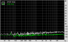
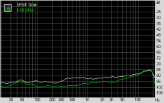
I finally managed to get hold of a half decent sound card (iMac running Parallels Win 7 and RMAA). The low frequency jitter in my previous plots was worrying me so thought I would re-measure with a better card. I'm sure that the THD results will improve further on an AP but I think this is good enough for now.
Attachments

Ian,
What do you approximate it would cost to produce the pcb board as you designed it? If you were to do a run of one hundred what do you estimate would be the cost? Molding the housing would be something else but that could be a simple mold to make the two halves in a few different processes.
Steven
What do you approximate it would cost to produce the pcb board as you designed it? If you were to do a run of one hundred what do you estimate would be the cost? Molding the housing would be something else but that could be a simple mold to make the two halves in a few different processes.
Steven
a 6 layer PCB in this price bracket in smallish numbers would be unworkable commercially IMO, particularly using a lesser known dac chip. the WM8740 would definitely be a better choice commercially too. you can get reasonable pricing on 4 layer these days, but 6 layer isnt usually found on special anywhere, unless you have a facility that you know, such as where you got these done.
Last edited:
Hi Steven,
I just costed the BOM for 100 pieces and buying through UK distribution it works out at $165 (US Dollars) per board inc taxes (20% here) for the components. The PCB would be about $30 and SMT assembly would be about $60 plus the enclosure.
With these costs I think it would need to handle 24/96 Audio over USB and use a better DAC as Qusp mentions.
Qusp: I agree 6 layer PCBs are significantly more expensive than 4 but the extra layers are useful as an EMI shield. The unit is housed in plastic which can be more challenging to pass EMC compliance compared to using a metal enclosure. That's not say it can't be done in 4, and yes the prototype boards were expensive.
Ian,
Are the components less expensive in the US? On the plastic housing I imagine that they could be metal sprayed if you needed more shielding, it would probably need flame retardant material also? I could get materials that would me the UL V0 to V5 rating we use here for housings if you wanted me to hand make the parts. It sounds like you are already thinking of an upgraded design with the different dac chip?
Are the components less expensive in the US? On the plastic housing I imagine that they could be metal sprayed if you needed more shielding, it would probably need flame retardant material also? I could get materials that would me the UL V0 to V5 rating we use here for housings if you wanted me to hand make the parts. It sounds like you are already thinking of an upgraded design with the different dac chip?
The components may be slightly cheaper in the US but it's probably more beneficial for me to do a cost down of the design.
A plastic case can be sprayed with conductive coating so that may help if emissions are found to be too high.
Thanks for the offer to make the enclosure parts. Flame retardant material would be required and it's good to know that you know about that stuff.
For now though I think I need to revisit the design and change the DAC and go with an Asynchronous USB chip to be competitive in the market. This could take some time though as I have other priorities at the moment. But we'll see what the year brings!
Don't worry about it Ian, we will still be here when your ready to take another look at your design.
Steven
Steven
marce, I've sent the Gerber files over, feel free to comment.
Steven, That's the good thing about audio it doesn't move at such a fast pace, Silicon devices that were produced 10 years ago can still hold their own today if they were designed well. So I think I'll try and re-spin this product as time allows. I've started looking at the XMOS devices which have Eval Boards available from Digikey. Has anyone tried these parts? I guess I can search this Forum for advice.
My aim will be to get to single sided placement in 4 layers and use fewer components. The current component count is ~350 parts, 25 of which are 0R resistors for debug which can all go, so lots of work to do......
- Status
- Not open for further replies.
- Home
- Amplifiers
- Headphone Systems
- USB DAC & headphone Amp with 3D Printed Enclosure