DCV measured directly across pins 1 and 2 of the optocoupler (generally better than measuring with ground as the reference).
Q39, black probe on emitter, DCV on base and collector?
Voltage directly across D23?
Q39, black probe on emitter, DCV on base and collector?
Voltage directly across D23?
DCV across pins 1 and 2 of the octocoupler - 1.162V
Q39 with black meter probe on pin 1, pin 2 is -9.43V, pin 3 is -9.06V
Q39 with black meter probe on pin 1, pin 2 is -9.43V, pin 3 is -9.06V
Diode?
Black probe on the negative speaker terminal, DCV on the emitter of Q39.
With a Vbe of -9v, Q39 is defective.
Black probe on the negative speaker terminal, DCV on the emitter of Q39.
With a Vbe of -9v, Q39 is defective.
Ok, I removed Q39. I have replaced this transistor already but after I replaced it, I found the R130 22K resistor to be open. At the time I replaced it and thought no more of it.
Q39 is in fact reading as a diode from the collector to the base.
I replaced Q39 and now the amp is oscillating. However, there looks to be a problem still.
When probing after R146, the first photo is what I get. If I remove C75 to test, will that cause damage to the drive circuit? The second photo is when I probe the base of both Q45 and Q54.
Edit. My scope is AC coupled
Attachments
Removing the capacitor may reduce the deadtime and cause the outputs to fail.
Use your scope in differential mode so you can use DC coupling.
Use your scope in differential mode so you can use DC coupling.
Am I to use Math functions with two probes? I can use math channel 1 - channel 2. I usually just AC couple to see the pattern large and use a DVOM to verify voltage.
Checking drive without DC coupling is as near useless as it can be. Why not use the scope to it's best?
Yes math function on digital scopes but they vary on specific settings. All you have to do is invert the second channel on analog scopes.
Yes math function on digital scopes but they vary on specific settings. All you have to do is invert the second channel on analog scopes.
I can invert the second channel on this scope too, even though it’s digital.
When checking the bad drive side at the cap, I get picture one. The not so bad side I get picture two. I’m going to assume I need a new cap. I’m not totally sure how to test caps this way. I removed it earlier on in the testing and tested it with an LCR meter and it said it was OK. Just because it measures OK doesn’t mean it is….
When checking the bad drive side at the cap, I get picture one. The not so bad side I get picture two. I’m going to assume I need a new cap. I’m not totally sure how to test caps this way. I removed it earlier on in the testing and tested it with an LCR meter and it said it was OK. Just because it measures OK doesn’t mean it is….
Attachments

When you test the drive in differential mode, you place ch1 on the gate and ch2 on the source of the output transistor. The vertical amplifier should be set to 5v/div.
The cap is introducing deadtime.
The cap is introducing deadtime.
The drive pattern that I’m getting though, looks as if something after R146 is pulling an NPN transistor down in the drive circuit. I have replaced all the transistors in the drive circuit so far.
I’m not sure if I understand what test I’m performing to check where the problem is occurring.
Forgive me if I appear to be stupid, but I’ve never used a scope in differential mode before.
I’m not sure if I understand what test I’m performing to check where the problem is occurring.
Forgive me if I appear to be stupid, but I’ve never used a scope in differential mode before.
Differential mode, after setting it up, is nothing more complex than using a multimeter. You use two probes that show the difference between two points. This eliminates the DC component when the test point is floating or biased well off of ground.
The important voltage on the gate of an FET is the voltage with reference to the source terminal. Channel 2 sets the reference. Ch1 is the signal with reference to ch2. As always, the signal will be between about 5 and 15v. This gives the cleanest view of the signal that you can get. You can see if the drive is going back to the reference point (not possible with AC coupling). You can also clearly see the amplitude (not possible in AC, especially for the high-side drive).
For my scope, I left it set up in differential mode. If I wanted to use one probe (most audio and PS signals), I used one probe. If I wanted/needed to check drive on a floating or DC biased point, I simply used the second probe. The only difference was having to place the ch2 probe on the reference that was something other than ground. Otherwise, the second probe was unused.
I use the multimeter that way. I put my black probe on the source of the output transistor and I get like 4.168V. When I do it with my scope it’s all over the place.
I put my scope in math mode, channel a - b. I put channel a on the source, and b on the gate. This is what I get.
If I connect the ground of my scope to the DC ground of my power supply, weird things start to happen.
I put my scope in math mode, channel a - b. I put channel a on the source, and b on the gate. This is what I get.
If I connect the ground of my scope to the DC ground of my power supply, weird things start to happen.
Attachments
The scope's chassis ground shouldn't make a difference. I'd leave it connected to the 12v power supply ground terminal.
In differential mode, you should only have a single waveform (like when using a single probe) when using both channels (two probes). Some digital scopes make this far more difficult than it needs to be but after you spend the time to get it right, you know what to do the next time.
In differential mode, you should only have a single waveform (like when using a single probe) when using both channels (two probes). Some digital scopes make this far more difficult than it needs to be but after you spend the time to get it right, you know what to do the next time.
Is there a workaround that I could employ for now? My scope is not making this diagnosis very easy. My pattern that was AC couples isn’t a good pattern to check the drive circuit?
Drive signals MUST go back to the voltage on the source terminal. You can't check that in AC mode.
All AC mode can tell you is that you have a signal and the amplitude... but the amplitude of the drive for the high-side is dodgy at best. You can compare the readings g-s for the high and low-sides and get a rough idea whether the drive is OK. If they seem OK and the amp doesn't draw excessive current and the outputs don't run hot, you can assume that all is OK. That said, differential mode tells you instantly whether all is well, or not.
All AC mode can tell you is that you have a signal and the amplitude... but the amplitude of the drive for the high-side is dodgy at best. You can compare the readings g-s for the high and low-sides and get a rough idea whether the drive is OK. If they seem OK and the amp doesn't draw excessive current and the outputs don't run hot, you can assume that all is OK. That said, differential mode tells you instantly whether all is well, or not.
This is what I get when I couple DC, and move the trace up to where I can see it. Best this scope can do until I either float the scope (which I don’t want to do) or get differential probes.
The amp draws 2.0A of current as of now, nothing is getting hot. I’m going to install the transistor I removed to get the optocoupler working normally and put a speaker on it to see what it does.
I still can’t verify output waveform unless I have differential probes can I?
The amp draws 2.0A of current as of now, nothing is getting hot. I’m going to install the transistor I removed to get the optocoupler working normally and put a speaker on it to see what it does.
I still can’t verify output waveform unless I have differential probes can I?
Attachments
I don't know what point in the circuit you're testing. I test at the outputs.
Before installing the outputs, you can test the high-side drive without differential mode.
Since this is a relatively low-voltage amp, you can raise the display (DC coupling, lowest possible vertical amplifier setting) until low rail is at the lowest reference line on the display, then probe the signal for the low-side. You could use both traces (one probe on the negative rail and the other on the gate).
When thinking about differential mode, think about your multimeter and how desirable it would be to use if you always had to have the black probe on ground.
If you decide to never use differential mode, you will be in the company of virtually 100% of the other scope users out there.
When I installed the rest of the optocoupler circuit, the amp came up as normal.
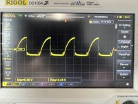
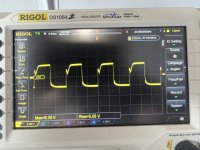
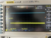
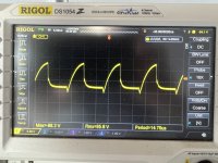
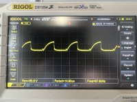
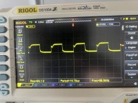
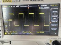
Picture 1 is at the first output fet gate (outputs are all installed) in the row, picture 2 is after R146 to the rest of the drive circuit to the fets. Picture 3 is at Q41 at the emitter (pin 1). When checking everything with a thermal imager, there’s nothing getting hot in the drive circuit at all.
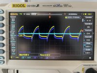
Finally the last photo is of the drain on the output fet where the gate is shown in photo 1. To me it looks dodgy but nothing is getting hot…..
This is DC coupled with the trace position adjusted so that you can see it on the scope screen.
Picture 1 is at the first output fet gate (outputs are all installed) in the row, picture 2 is after R146 to the rest of the drive circuit to the fets. Picture 3 is at Q41 at the emitter (pin 1). When checking everything with a thermal imager, there’s nothing getting hot in the drive circuit at all.
Finally the last photo is of the drain on the output fet where the gate is shown in photo 1. To me it looks dodgy but nothing is getting hot…..
This is DC coupled with the trace position adjusted so that you can see it on the scope screen.
Attachments

- Home
- General Interest
- Car Audio
- US Amps AX3200DE Schematic