Sorry for the delay.
1.2 is about what I'd expect. I've seen about 1.25, generally.
I don't understand the muting circuit as you've described it. N-channel jfets need negative gate voltage to switch off.
I also don't understand why you have positive voltage on pin 4 of the optocoupler. Is it still positive after the end of the mute delay?
The outputs could be an issue. I know that you can't go from the TIP to the FJA without problems. The MJE to the FJA could cause some issues, especially the bias stability.
I'd expect a driver problem but the problem could be any component back to the muting transistor. I'm assuming that you have confirmed that you have clean audio at the muting transistor.
Hello Perry,
as described before, the Optocoupler was the cause, that i havent any output. I changed the optocoupler, now i have a signal at bouth banks.
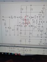
The jfet is pulling the input signal to ground, at the beginning of the first input stage. See the last diagram. I rechecked the voltages at the optocoupler. Ground is sec. center. At Pin 6 i have now -15VDC, the same as on Pin 4. It stays on all the time.
Now iam troubleshooting the repaired channel with this sawtooth problem.
It seems, that there is a new transitor leaking in the second stage from the negative side..
Also sometimes i have dc offset... so there is still an intermittend problem.
as described before, the Optocoupler was the cause, that i havent any output. I changed the optocoupler, now i have a signal at bouth banks.
The jfet is pulling the input signal to ground, at the beginning of the first input stage. See the last diagram. I rechecked the voltages at the optocoupler. Ground is sec. center. At Pin 6 i have now -15VDC, the same as on Pin 4. It stays on all the time.
Now iam troubleshooting the repaired channel with this sawtooth problem.
It seems, that there is a new transitor leaking in the second stage from the negative side..
Also sometimes i have dc offset... so there is still an intermittend problem.
Can you install the surviving original outputs to see if the replacements are causing a problem?
The optocoupler is likely using only terminals 4 and 5. 6 is a base connection if you want to bias the optocoupler nearer to conducting.
The optocoupler is likely using only terminals 4 and 5. 6 is a base connection if you want to bias the optocoupler nearer to conducting.
I will see, if i find some surviving outputs.. Now iam measure in the first stage and second stage. The signal is good at the base of the first transistor. At the collector its allready disturbed..
There may not be any point between the base/emitter of the input stage and the output transistors that looks like audio.
You can compare to the other channel.
You can compare to the other channel.
It seems, that the new outputs are not compatible... The old ones are from ON Semi..
but all transistors are damaged. I will use two from the working channel to recheck...
If this is the problem, which transistors do you recommend?
but all transistors are damaged. I will use two from the working channel to recheck...
If this is the problem, which transistors do you recommend?
I have no known good sub.
Did the defective channel work normally with outputs from the other channel?
Did the defective channel work normally with outputs from the other channel?
No, its still the same... I found, that the other both optocouplers have different voltages at pin 1 and 2 when a signal is apllied.. The disorted channel has about 20v at this pins, the good channel only 10v
I don't know right now. But iam not sure if this is causing my problem.
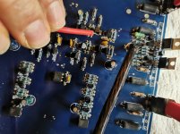
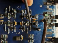
See attached picture. The left transistors signal is OK, the right one bad and pulled down. At the schematic the good side is 1,the bad side 2..
If I remove q105, the signal is good... But the transistors are OK. The 15 v is also present.
See attached picture. The left transistors signal is OK, the right one bad and pulled down. At the schematic the good side is 1,the bad side 2..
If I remove q105, the signal is good... But the transistors are OK. The 15 v is also present.
Attachments

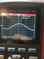
So, if i measure at the base on the outputs, it pulls my signal down to negative and fully disorted. But, if i reduce the frequency to about 200Hz, everything is fine. As more as i increase the frequency, as more it goes to negative, reduce the amplitude and disort more.
Found the problem... I think for the future i need some glasses....I made a bridge, at a place where no bridge should be.-..
If you're serious about glasses, the drug store cheater glasses can help greatly. Here, you can get 3 pairs for $8 and they're decent quality.
As a side note, bridges are easy to make. Some of the most dreaded tech support threads start with... I resoldered all of the connections and now I have another problem.
If you use the FJA transistors, run the amp through its entire thermal range and confirm that the bias holds. The On-semi type transistors require different biasing than the FJA types. The difference may or may not cause you any problems.
- Home
- General Interest
- Car Audio
- US Amps 2000x