Next week i will get the Klipsch RP-160M they are 97db
i hope it will be better
i have a pair of these loudspeakers being powered by a Boyuu A9 DIY built amplifier. I am very happy with them.
They should be fine with your amp.
So I found some info on your amp . . .
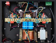
From taking quick look at the pic I assumed that it's a PP (push-pull) amp since it has two output tubes per channel. Turns out it's actually a PSE (parallel single-ended).
That's unusual in a commercial amp and I'm guessing it was done because they had a pile of SE transformers that would work. From a design standpoint PP would probably have some advantages (I'm no expert) such as noise cancelation, but their "design philosophy" (I use the term very loosely) seems to be to use parts they can get cheap in order to maximize profit. Following proven design protocols is not a major consideration.
Many owners of these cheap Chinese amps suggest that the first thing to do is replace all the cheap tubes that come with these with better quality tubes.
I looked up the 6P1 tube and it's a tube only produced in China and Russia with apparently no American or Western European equivalents. Electrically, the closest US tube would be the 6AQ5, which is a 7 pin, or the 12AB5, which is a 9 pin, like the 6P1, but it has a 12.6v heater and a different pinout.
So your possibilities are limited to using either the Chinese or Russian tubes. I suppose you could rewire the sockets and install a 12v transformer and use 12AB5s but it's probably more than you'd want to deal with.
If you want to try the Russian version, see if you can find the -EV or -EB version, that's the military spec one and should be better built and last longer. They are not expensive, so at least that's a plus.
I'd be more concerned about their parts choices considering the issues that are prevalent in some of the other cheap Chinese amps.
One of the main issues, as pointed out earlier, is that the Chinese use PTs whose primary is rated at 110v (220v in Europe) and the typical wall voltage is higher. The result is that all the voltages in the amp will be higher and in some cases this will cause problems.
I suggest that you buy a decent digital multimeter and measure your wall voltage if you haven't already. Unfortunately, you'll probably need a soldering iron too.
OK, I know you're probably just a typical buyer of these cheap Chi-Fi amps who expects that a commercial product is well designed and can just be plugged in and used without issues. Unfortunately, that turns out to be wishful thinking when it comes to many of these amps.
Numerous threads on various audio forums document a host of problems with the cheaper offerings from China.
These include: hum issues, undersized power transformers that overheat, rectifier tubes that arc and fail, oversized power supply capacitors, resistors that burn up, the use of counterfeit "name brand" parts, amps that put out about half the power that they claim, etc, etc.
That's all I have time for right now. I'll post more later.
Last edited:
Wow
This is a great information, thank you very much.
Is Yaqin brand also suffer from all this issues ?
This is a great information, thank you very much.
Is Yaqin brand also suffer from all this issues ?
6P1 is a copy of Soviet 6П1П that is 6V6 in a glass bulb. Excellent tube, why would you want to replace it by something worse?
Wow
This is a great information, thank you very much.
Is Yaqin brand also suffer from all this issues ?
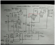
So I found a schematic! It was posted as part of an Amazon review in which the buyer said it was sent to him after he requested it from the seller.
It's hand drawn, which seems odd since this is a commercially sold amp and not some DIY project. Unfortunately, the only voltages listed are the cathode voltages. And it looks like they used a couple of different cathode resistor values on the input tube.
Based on those voltages, according to the schematic, the amp draws between 123 and 125 mA. The limit for the 5Z4P rectifier is 125 mA. So, according to the schematic, they're running the rectifier right at the limit in terms of current.
But that assumes that you actually have 220v at your wall socket, which you probably don't. It's probably over 240v. This is why the use of PTs that have 220v primaries can cause problems when you actually have higher wall voltage.
But that's not the only problem.
Just as on some of the other Chinese amps the first cap after the rectifier is way too large a value. This can result in arcing and even blown rectifiers. And that's if you're lucky. It can also cause transformer damage, if you're not so lucky.
The data sheet for the 5Z4P says the maximum value for the first cap should be 4 uf, yes 4. According to the schematic they're using 150uf.
On amps that are drawing considerably less current than the rectifier allows, you can get away with using a first cap that is a bit larger but they go way beyond that. The "designers" of these amps apparently don't bother to read tube data sheets. Or, if they do read them, they ignore them and just use whatever parts result in the most profit.
Now, I do see on the schematic that some other rectifiers are listed, including the 5Z3P which can handle more current but it also draws more heater current (3A vs 2A) and who knows how much the PT is actually designed for since no current specs are shown. IF the winding is good for 3A, the 5Z3P can be used but the transformer will run hotter. If the winding is really a 2A, the additional stress could destroy the PT. So you takes your chances. In addition the 5Z4P is indirectly heated, which provides a slow start while the 5Z3P is not slow start.
So, what can be done?
Switch to a 5AR4 / GZ34 rectifier. It has a 1.9A heater and can handle 100 mA more current than the stock 5Z4P rectifier. Plus, it provides a slow start.
The 5AR4 also can be used with a larger input cap value, but not 150uf. That's still way too much. I'd use a 47uf 450v first cap. The second 150uf cap can be left alone. Just replace the first one.
After making those changes all the voltages need to be measured to make sure that the output tubes aren't being run too hard and that the heater voltages aren't too high. If the measured voltages indicate a problem then further adjustments can easily be made.
Once the design flaws have been taken care of, this amp has a lot of potential. There's plenty of space under the chassis so it's not a difficult amp to work on. Also, since it uses point to point / tagboard construction any modifications to the circuit will be easy. That's not the case with amps that use circuit boards.
I don't know much about the Yaquin amps but I'd suggest putting this one in shape and then seeing how well it works with the Klipsch speakers.
Attachments
6P1 is a copy of Soviet 6П1П that is 6V6 in a glass bulb. Excellent tube, why would you want to replace it by something worse?
The tube I was suggesting as a possible replacement for the stock Chinese 6P1 is the Russian military version. Maybe the stock tube is fine, I don't have any experience with it.
Perhaps I'm biased but I'm a bit skeptical of the Chinese tubes. Personally, I would much rather use a real Russian tube than a Chinese copy of a Russian tube.
From reading numerous posts about cheap Chinese amps, I know that owners often replace the tubes almost immediately and claim that whatever replacement they used is an improvement. Many look for American versions. I was trying to point out that, while the 12AB5 would work electrically, it wouldn't really be practical.
Add input source to amp..
Hello friends,
Is it possible to add this board to the amp ?
tank you
hifi audio 4 pairs RCA input Source Selector Signal Selector Switching For Audio Preamp Power Amplifier DIY Kit
Hello friends,
Is it possible to add this board to the amp ?
tank you
hifi audio 4 pairs RCA input Source Selector Signal Selector Switching For Audio Preamp Power Amplifier DIY Kit
Need your help for changing caps...
Hello,
On my amp there is two caps connected together (vishay 450V 150uF )
I want to change them to better one's
Mundorf_MLYTIC HV_MLGO450
is this capacitor i need to order ?
Thank you very much and sorry for my bad english..
Hello,
On my amp there is two caps connected together (vishay 450V 150uF )
I want to change them to better one's
Mundorf_MLYTIC HV_MLGO450
is this capacitor i need to order ?
Thank you very much and sorry for my bad english..
Changing power supply caps also depends on whether your amp has a tube rectifier. Also the arrangement of the filter caps. So, if you can give more information about your amp would be most helpful about a more informed recommendation.
Thank you DAK808,
150uf is on the list there
My amp 6p1 Douk audio..its Chinese.
Amp schema
https://www.diyaudio.com/forums/att...62140d1560212905-upgrade-douk-6p1-pse-6p1-png
Thank you
150uf is on the list there
My amp 6p1 Douk audio..its Chinese.
Amp schema
https://www.diyaudio.com/forums/att...62140d1560212905-upgrade-douk-6p1-pse-6p1-png
Thank you
Why do you think you need to replace these ? What is the symptoms ?Hello,
On my amp there is two caps connected together (vishay 450V 150uF )
I want to change them to better one's
Mundorf_MLYTIC HV_MLGO450
is this capacitor i need to order ?
Thank you very much and sorry for my bad english..
Why do you think you need to replace these ? What is the symptoms ?
Ahem… I predict there are no symptoms related to the capacitors in the power supply. Rather, it “feels like” there is a deep desire just to change things up that are simple to rearrange. CIBIC¹. CIBIC duty…
But then that's probably 80% of what goes for desire here on DIY.
Including my motivations from time to time.
O well … to be inspired again!
Just saying,
GoatGuy ✓
PS: changing out dual 150 µF caps for far more expensive 100 µF caps should at least follow the 3 to 2 math … 3 of the 100 µF in parallel for the two 150 µF presently in place.
This of course will be a McGillicuddy of a change out if the amplifier is built just on a piece of copper plated fiberglass.
________________________________________
¹ Change It Because I Can
I want to upgrade to better quality capacitors
i want to change 150uf with 150uf just much better quality
i want to change 150uf with 150uf just much better quality
I suggest to lower the value of the first capacitor (connected to the rectifier tube pin) to 33uF, and rise the value of the capacitor after the choke to 270uF. I have done this on a BL-02 amplifier, and then I have been able to replace the rectifier with a relatively expensive one without the fear to blow it up in a few months. This would have been a certainity with the stock 150uF filter capacitor. No need to use expensive Hi-Fi capacitors here, Nichicon would serve the purpose fine. Save the money for better output transformers and/or tubes.
- Home
- Amplifiers
- Tubes / Valves
- Upgrade Douk 6p1