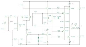
The input stage is running at ~5mA/side, so that base is covered, since the drop in each current mirror degeneration resistor is 166 mV.
I completed a layout yesterday and pulled the trigger at PCBWay. The board will handle 3 X TO-247 Darlington or 2 X TO-247 mosfet/side. It is currently sized to fit between the flanges of my Conrad heat sinks. If the design works out as expected, I'll consider a more universal layout per the templates provided. Right now, the layout is for the enhanced circuit version with current mirror loaded diff input and Darlington VAS. I am using Toshiba TTA004B and TTC004B for the VAS stage to handle the extra dissipation.
Last edited:

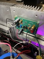
Gottem boards.... I will likely start with the Darlington output version of the design using 3X each side TIP142G and TIP147G from onsemi. There are a couple of minor board issues that can be fixed with creative jumpering. First thing I will do when I get home will be to drop a board between the flanges of my Conrad heat sink to check fit.
Ed - Also ordered some 2N5401/5551 via E-pay for the low power transistors on this build. VAS will be TTA004B and TTC004B as previously mentioned.
Ed - Also ordered some 2N5401/5551 via E-pay for the low power transistors on this build. VAS will be TTA004B and TTC004B as previously mentioned.
Last edited:
Oh yeah, the boards fit between the heat sink flanges. I've had that particular pair of Conrad heat sinks for years - it's time to put them to work.
I also got my 2n5401s and 2N5551s today - some assembly will be done this weekend. The 5401s and 5551s are pretty generic-looking.....
Last edited:
Not yet - I think I might hold off until I get the board mounted down on its intended heat sink.
Pass DIY Addict
Joined 2000
Paid Member
It's exciting to read about this update! Great work! The a40 is the first amp I built after finding this forum more than 20 years ago. I haven't fired it up in a little while - time to give it another listen!
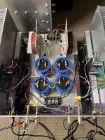
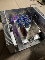
Figured I'd put this here, as it is about an Updated A40. Recently finished this update with the help of WhiteDragon. With a slight modification to the input scheme, and 2 pair of MJH6284/87 darlingtons, I'm able to run it at 2A with 30V rails. Of course the sinks are lukewarm at best. With an eye towards a 3A bias, I'd like to add another pair of outputs, and keep those TO-247's safe. Is it as simple as adding another pair and maybe increasing the Re to say 0.75R? Are there any other values that may need adjustment? As it is, I dare say it may be better than my first A40 clone.
thanks,
John
thanks,
John
Attachments
WrenchOne
Thanks for your efforts. Saw that you had some boards made. Are those gerbers available to the community or do you have other plans for them. I would be interested in building a newer version of this amp. Still love the old one though.
Thanks for your efforts. Saw that you had some boards made. Are those gerbers available to the community or do you have other plans for them. I would be interested in building a newer version of this amp. Still love the old one though.
The board was made to fit between the flanges of a double-flange Conrad cast heat sink, with the output Darlingtons standing up. However, it would probably work with the devices lying down on a wider heat sink. I only had 5 boards made. What I need to do to proceed is to figure out how to drill the flanges to fit the TO-247 Darlington packages. Until I figure that out, the project is pretty much stalled. No Gerbers will be made available.
I have used Siliconix 2N5912 matched FETs on of the A40 works great no need to change biasing either. I still have a bunch of Lambda Darlingtons if I can find them, there are all TO3 cans.
Sorry JohnFigured I'd put this here, as it is about an Updated A40. Recently finished this update with the help of WhiteDragon. With a slight modification to the input scheme, and 2 pair of MJH6284/87 darlingtons, I'm able to run it at 2A with 30V rails. Of course the sinks are lukewarm at best. With an eye towards a 3A bias, I'd like to add another pair of outputs, and keep those TO-247's safe. Is it as simple as adding another pair and maybe increasing the Re to say 0.75R? Are there any other values that may need adjustment? As it is, I dare say it may be better than my first A40 clone.
thanks,
John
For not replying and updating your request for 6 output devices
To match the thermal stability goals of the original design
for Class A bias is closer to 1 ohm for 6 output transistors.
For Class A/B .82 ohm even .68 would be ok
Original design is using .68 ohm per transistor
Parallel degen is .68 divide by 2 = .34 ohms
For 3 pairs
1 ohm divide by 3 = .33 ohms
To drive 6 output devices would simply increase
the durability of the second gain stage driving them
and likewise transistor used to apply constant current
.
T4 and T5 have been changed from T0-92 devices to
more thermal Friendly T0-126 package.
Degen resistor slightly lowered to increase current
for the constant current source simply 100R 5%
lowered to 91R 1% to slightly raise current.
options included in notes to adjust idle with set resistors
and option to improve DC offset on output.
Original design approx 8 to 10 mV on output
Can be improved with one resistor change to be
around 3 mV to under 1 mV
of course click to enlarge

Last edited:
They should work, but they are much faster compared to the original. Keep that in mind when wiring the output stage.Sanken 2sb1647/2sd2560
- Home
- Amplifiers
- Pass Labs
- Updated Pass A40 Design