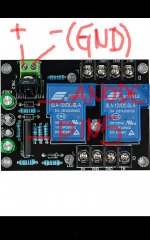
look to me - if you are looking at the green connector, GND would be on the left (closer to the relays) and DC on the right hand side (terminal closest to the edge of the board)
Take your DMM and see which terminal goes to the diode (1N4007??) directly behind the 7812 regulator. That would be the positive terminal.
edit - saw post #33 and I agree
Take your DMM and see which terminal goes to the diode (1N4007??) directly behind the 7812 regulator. That would be the positive terminal.
edit - saw post #33 and I agree
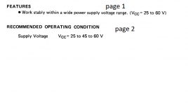
Your DC VCC must be minimum around 15V to make LM7812 work correctly
(check the datasheet)...
https://www.ti.com/lit/ds/symlink/l...ll-mousermode-df-pf-null-wwe&ts=1589391635135
I've seen/tried modules with 7812 powered by less than 12V,
and LM was passing this voltage trough, so it kind of worked,
but you don't want to do this with speaker protection 🙂
Ok, if i understand, for this module working fine and safe, i can power DC voltage 15v?
It safe if i run with DC 15v, or it will run hot and give me some problems?
Sorry asking all this but i don't have to much knowledge.
Last edited:
look to me - if you are looking at the green connector, GND would be on the left (closer to the relays) and DC on the right hand side (terminal closest to the edge of the board)
Take your DMM and see which terminal goes to the diode (1N4007??) directly behind the 7812 regulator. That would be the positive terminal.
edit - saw post #33 and I agree
If you agree with me, my schematic in the post #33 it's ok, right?
Attachments
PIN 8 (Vcc) of the upc chip takes max 8V.
The example schematic they show in the datasheet is powered via resistor.
Now, depending on that resistor, the board might work with 12V.
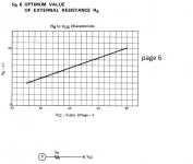
Yes, R8 is required to work from 25 V to 60V and it works properly also. Have built 2-3 myself VDC 35V & 56V.
Even the plot of R8 selection starts at 25V and ends at 60V.
There must be a reason why datasheet recommends 25V to 60V , Anybody know why?
Attachments
If you agree with me, my schematic in the post #33 it's ok, right?
I agree. and as far as current, you only need 50-150mA, very little.
Ok, if i understand, for this module working fine and safe, i can power DC voltage 15v?
It safe if i run with DC 15v, or it will run hot and give me some problems?
Sorry asking all this but i don't have to much knowledge.
I think it will run fine at 15V. It will not run hot at this voltage.
After you connect the power, measure voltage on each pin of LM7812
(between ground, and pin).
Middle pin is ground (0V), one of them is your input, another one should be 12V.
Yes, R8 is required to work from 25 V to 60V and it works properly also. Have built 2-3 myself VDC 35V & 56V.
Even the plot of R8 selection starts at 25V and ends at 60V.
There must be a reason why datasheet recommends 25V to 60V , Anybody know why?
I've build few of these things, and for me - as long as you recalculate R8 and
voltage at pin 8 is under 8V (I usually go for 5V) it works fine.
Please note, that relays are usually powered directly (or via small R) from the higher voltage, taken BEFORE the resistor.
I guess maybe that's why they recommend higher voltage - to provide juice for relays.
The chip itself consumes very little current..
There must be a reason why datasheet recommends 25V to 60V , Anybody know why?
I believe those values are typical for audio amplifier power rails. uPC1237 was designed specifically for that use, nothing else.
I think it will run fine at 15V. It will not run hot at this voltage.
After you connect the power, measure voltage on each pin of LM7812
(between ground, and pin).
Middle pin is ground (0V), one of them is your input, another one should be 12V.
Why do i need measure the voltage?
If i plug DC power 15v (turn on) in the module and measure the pins between middle pin "GND" and the other pins it doesn't damage the "LM7812"?
Why do i need measure the voltage?
If i plug DC power 15v (turn on) in the module and measure the pins between middle pin "GND" and the other pins it will damage the "LM7812"?
To verify that it works, and you connected everything correctly.
By measuring voltage on 'live' board of this kind - you not gonna
damage anything.
Unless you short something... 🙂
To verify that it works, and you connected everything correctly.
By measuring voltage on 'live' board of this kind - you not gonna
damage anything.
Unless you short something... 🙂
Do i need power up the module with DC 15v and put the black terminal of DMM on middle pin (GND) of the transistor and with terminal red of DMM measure the pin1 and pin3, right?
I'm newbie, and my knowledge is not to much.
Sorry asking all this.
Best regards.
Do i need power up the module with DC 15v and put the black terminal of DMM on middle pin (GND) of the transistor and with terminal red of DMM measure the pin1 and pin3, right?
I'm newbie, and my knowledge is not to much.
Sorry asking all this.
Best regards.
yes - if you look at the front of regulator. GND is middle, input (15V) is left pin and output (12V) is right pin. Google images is your friend.
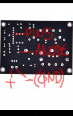
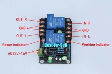
Hi my dears DiyAudio lovers. I already receive my UPC1237 Speaker protection board and plug this module with DC 15v but i cannot listen any music through the speakers. I connect the module the right way but i cannot listen any music through the speakers. Anyone can help me find and fix this problem? My module is that on the picture.
I hope anyone can give me a little help.
Best regards and good health for all members.
I hope anyone can give me a little help.
Best regards and good health for all members.
Attachments
Hi my dears DiyAudio lovers. I already receive my UPC1237 Speaker protection board and plug this module with DC 15v but i cannot listen any music through the speakers. I connect the module the right way but i cannot listen any music through the speakers. Anyone can help me find and fix this problem? My module is that on the picture.
I hope anyone can give me a little help.
Best regards and good health for all members.
First, check voltages at the DC regulator LM7812.
Are you getting POSITIVE +12V (measured from GND) at the output of the regulator?
First, check voltages at the DC regulator LM7812.
Are you getting POSITIVE +12V (measured from GND) at the output of the regulator?
I'm getting this values from the ground (-) of the terminal of input voltage:
Input PIN: 15.7v
GND: 0v
Output PIN: 12.2v
I don't understand what means common ground in the description of this item shared by the seller. I connect + and - from the output speaker (L+ L- / R+ R-) of the amplifier board to the input of the speaker protection, and from the output from the speaker protection to the terminal of my speakers.
I don't understand why this doesn't work.
Can you give me a help my dear minek?
Best regards and good health for you.
Attachments

Last edited:
I'm getting this values from the ground (-) of the terminal of input voltage:
Input PIN: 15.7v
GND: 0v
Output PIN: 12.2v
I don't understand what means common ground in the description of this item shared by the seller. I connect + and - from the amplifier board to input of the speaker protection, and from the output from the speaker protection to the terminal of my speakers.
I don't understand why this doesn't work.
Can you give me a help my dear minek?
Best regards and good health for you.
What kind of amp you have?
Is it bridged or not?
For normal, non-bridged amps, you need to connect
Left SPEKAER OUTPUT to the "IN L" and
right SPEKAER OUTPUT to the "IN R".
Ground of the speaker need to be connected to the ground (GND) of the protection board. One wire is enough.
Ground of the DC power supply (15V for this protection board), also need to be connected to the GND of this board. That is done via "AC" input connector, correct?
Are you using the same power supply as for your amp? Or is it separated unit?
I don't understand why the seller mentions this 'common ground' and states that you need to buy 2 boards.
I think this is some kind of mis-translation 🙂
Perhaps he means that both channels of your amp HAVE TO share
the same ground...
That's fine but normal, non-bridged amps.
My amplifier board is a TDA7498E.
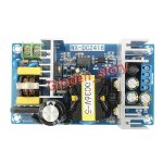
I use the same power supply of my amp but i send it first to a buck converter to decrease the voltage, because i use a power supply DC 36v to power my amp, and 15v with the buck converter to the speaker protection.
Do i need to connect the GND (-) of buck converter into the GND in and out of the speaker protection? Can you explain me? My knowledge is not to much.
Best regards and good health my dear minek.
My amplifier board is a TDA7498E.
I use the same power supply of my amp but i send it first to a buck converter to decrease the voltage, because i use a power supply DC 36v to power my amp, and 15v with the buck converter to the speaker protection.
Do i need to connect the GND (-) of buck converter into the GND in and out of the speaker protection? Can you explain me? My knowledge is not to much.
Best regards and good health my dear minek.
I don't think it will work with buck converter.
These converters usually ISOLATE input from output, so GND output from the converter is not the same GND as of the amp (or GND input of the converter).
You can't join them at the protection board.
One option would be to use separate rectifier connected directly to the transformer (assuming your PSU has a transformer), and feed buck converter from that rectifier, and then connect output of the buck converter to PLUS and GND of the protection board.
Or, you can find NON ISOLATING buck converter (common ground for input and output of the converter).
Or, instead using buck converter, use small regulator (e.g. Zener + transistor + heatsink) - but it will waste a lot of energy (heat) to drop 20V at at least 200mA...
Or, just a last thought, maybe out GND of the buck converter CAN be connected to input GND?
Last edited:
I don't think it will work with buck converter.
These converters usually ISOLATE input from output, so GND output from the converter is not the same GND as of the amp (or GND input of the converter).
You can't join them at the protection board.
One option would be to use separate rectifier connected directly to the transformer (assuming your PSU has a transformer), and feed buck converter from that rectifier, and then connect output of the buck converter to PLUS and GND of the protection board.
Or, you can find NON ISOLATING buck converter (common ground for input and output of the converter).
Or, instead using buck converter, use small regulator (e.g. Zener + transistor + heatsink) - but it will waste a lot of energy (heat) to drop 20V at at least 200mA...
My PSU is that on the picture.
If i understand i cannot use this speaker protection module with DC voltage?
Attachments
- Home
- Amplifiers
- Solid State
- UPC1237 Speaker protection board: Current requirements