There have been some recent posts on these chips. Apparently the uPC has a few different versions, most of which are obsolete or will be soon. One post mentioned that of the 4 NTE's he got from China, 3 were bad. I wouldn't mind using the NTE but it only goes to a 60 VDC rail and I need to go to at least 80 and preferably 100VDC.
At the moment I'm playing with a variation of the common discreet circuits. Most of them have some kind of a detection circuit based around a couple transistors or a bridge rectifier that drives a couple transistors. I'd like to use a chip rather than a bunch of discreets as board space is very limited.
So I wonder, what chip is in common use these days? Certainly all of the surround receivers use something that is current.
I may be wrong, but I believe many (most?) modern protection is handled by a chip which also provides a host of other functions as well.
I'd consider Rod Elliot's board (it's very small), since integrated solutions seem to be disappearing.
According to the data sheet, the uPC1237 is also limited to 60V.
I'd consider Rod Elliot's board (it's very small), since integrated solutions seem to be disappearing.
According to the data sheet, the uPC1237 is also limited to 60V.
EchoWars said:
I'd consider Rod Elliot's board (it's very small), since integrated solutions seem to be disappearing.
According to the data sheet, the uPC1237 is also limited to 60V.
I like and have use Rod's board (his project #33). However I have a specific application and will be building up a board that have the relay(s) mounted on the board. I emailed Rod about licensing his circuit but he didn't respond. Although his board is good, component spacing is so tight that solder bridges are a real concern. This problem is magnified as he doesn't use a solder mask.
Well, I know you've used it because we've discussed it. Rod apparently had three design goals...simplicity, small size, and low cost. The latter is likely why there's no solder mask.
I wish I could help out, but I have next-to-no idea what the new stuff is using.
I wish I could help out, but I have next-to-no idea what the new stuff is using.
EchoWars said:I may be wrong, but I believe many (most?) modern protection is handled by a chip which also provides a host of other functions as well.
I'd consider Rod Elliot's board (it's very small), since integrated solutions seem to be disappearing.
According to the data sheet, the uPC1237 is also limited to 60V.
I use the uPC1237 myself, I have no problems buying them from my local supplier. It works exactly as described in the data sheet. You need to figure out some resistor values if you want symmetrical offset protection. I use one uPC per channel as they are so cheap and it helps to keep channels and channel wiring separate.
Indeed it is limited to 60V but that should be trivially easly fixed with a couple of resistors. Just make sure the supply to the chip never gets above 60V.
Jan Didden
janneman said:
I use the uPC1237 myself, I have no problems buying them from my local supplier. It works exactly as described in the data sheet. You need to figure out some resistor values if you want symmetrical offset protection. I use one uPC per channel as they are so cheap and it helps to keep channels and channel wiring separate.
Indeed it is limited to 60V but that should be trivially easly fixed with a couple of resistors. Just make sure the supply to the chip never gets above 60V.
Jan Didden
I was thinking about that. A 30 volt zener from the 80V power supply would get below 60V. Are you thinking of using a voltage divider on the input to limit the voltage.
I plan to use the NTE7100 and my breadboard version seems to work okay. I plan to use a simple dropping resistor as shown in the UPC1237 datasheet.
d3imlay said:
I was thinking about that. A 30 volt zener from the 80V power supply would get below 60V. Are you thinking of using a voltage divider on the input to limit the voltage.
You want to limit the supply of course, not the input voltage. I think paulb above answered it.
Jan Didden
Hallo loek, I replied to your e-mail...
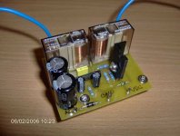
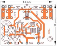
Nice layout Zeon... interesting the dual relay...
May I ask why you chose that over the single relay...? also does it still fall within the chip's output rateing to actualy handle two relays?
Nice layout Zeon... interesting the dual relay...
May I ask why you chose that over the single relay...? also does it still fall within the chip's output rateing to actualy handle two relays?
Personally i've never seen the point of using such IC's in a DIY design. Commercial offerings use them in order to save parts count and cost, but it's much better to do something discrete especially as these IC's often go obsolete.
These days it's often done discrete anyway, but usually strictly as a detector - this is then fed to the amp's microcontroller which controls the speaker protect relay and/or the power relay.
These days it's often done discrete anyway, but usually strictly as a detector - this is then fed to the amp's microcontroller which controls the speaker protect relay and/or the power relay.
uPC1237HA
I found them overhere Nico.
Thanks Jan and Nico for the help finding those chips.
Regards, Loek
I found them overhere Nico.
Thanks Jan and Nico for the help finding those chips.
Regards, Loek
Re: 3
zeonrider said:3
Zeon,
Nice work. I'm working on a similar project and have found that the voltage at pin 2 will not exceed a few volts which would allow for a lower voltage cap. Also, why use 2 in series when bipoars are available? I always subscribe to the notion that unused input pins on a chip are tied to ground or V+ to avoid noise issues. On mine I have a zero ohm resistor going to ground on pin1. I also brought out pin 1 to a terminal, through another zero ohm resistor so that it could be used at a later date in case I want to add an over current sense.
Regards zeoN_Rider
jaycee said:Personally i've never seen the point of using such IC's in a DIY design. Commercial offerings use them in order to save parts count and cost, but it's much better to do something discrete especially as these IC's often go obsolete.
These days it's often done discrete anyway, but usually strictly as a detector - this is then fed to the amp's microcontroller which controls the speaker protect relay and/or the power relay.
Jaycee
I agree with you that discreet would be desirable. In my application I have limited space for a board. I'm banking on this chip being available for a while since NTE has an equivalent.
jaycee said:[snip]Commercial offerings use them in order to save parts count and cost, but it's much better to do something discrete especially as these IC's often go obsolete.[snip]
Obsolescense is often a problem, although these chips, because a lot of manufacturers use them - will probably stick around some time.
In what way would a discrete circuit be better?
Jan Didden
janneman said:
In what way would a discrete circuit be better?
Small-signal transistors suitable for the job will always be available 🙂
- Status
- Not open for further replies.
- Home
- Amplifiers
- Solid State
- uPC1237/NTE7100