The small signal triodes will do far better than sand will for voltage amplification, and an mosfet output will work well too. you could do far worse.
but ok.. so you want to determine the turn ratio of your opt anyway. you only have a multimeter? Hope its a good one.
Read this: Output Transformer Impedance
It helps to have a variac. You really should not use a wall socket...
Also check out this fellow's youtube video: https://www.youtube.com/watch?v=Yzo3A-NywSs
I hope you are 100% certain which connections are primaries and which are secondaries.
Last edited:
So I have now figured out the OPTs. The main turns ratio is 33:1, that gives me 8,700 ohms for an 8ohm speaker or 4,350 for a 4 ohm speaker. They are physically quite small so I guess good for 5w or less and probably limited in bass response. Given the rest of my collection of bits any suggestions for a schematic?
Thanks
Caber 🙂
Thanks
Caber 🙂
Folks
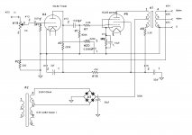
You've all been silent since I posted the schematic. Please let me know if you think this will or won't work. I want to set about breadboarding a single channel and would rather not have something let the smoke out🙂I am rather intrigued by the power supply using the OPT as a choke. Of course this was invented as a bit of commercial cost cutting but does have the advantage of reduced part count and as I have suitable OPTs it would be a bit of a waste not to try it. So outstanding questions are do I have B1 voltage correct? If so should I attempt to reduce it or change bias in some way to get into flatter area of the curve? Please help before I buld this and burn something 🙂
Avo111
Your schematic shows a special wound transformer. Part of the primary possibly being uses an a hum bucking (choke) or cathode feedback winding.
If you have the transformers and can figure out the b+ ground and plate terminals the resulting amp will result in about 3 watts output
If you have the transformers and can figure out the b+ ground and plate terminals the resulting amp will result in about 3 watts output
Last edited:
- Status
- Not open for further replies.