Measured all of them, but unfortunately a batch with minimal bandwidth. All measure 0.624~0.627fV. Took the 0.624fV x4 , but still 0.67V at base of transistors. Might buy another 100 pieces. I can use them and normally there's larger differences.Buy 100 1N4148´s, and test the forward voltage. Then chose the quad with the lowest fV 😉

Another option might be in the attachment. Not sure if it had the same voltage drop. Used it for a sony long time ago. Maybe someone with more knowledge can tell whether it is applicable? (Used BC550 instead of 2sd1585, got this info at audiokarma i guess)
Attachments
The 1N4148's are gold-doped, resulting in a lower Vf, among other things.
General-purpose, non-doped diodes like the OA202 in Europe, and similar JEDEC parts have a higher Vf: 1N646 comes to mind, but it is largish, and also has a relatively low Vf. There are other types, in a smaller glass case, but I don't have them in mind.
Other options are the BE junction of a small-signal transistor, but they tend to be more bulky (leave C open), a varicap diode, a high voltage avalanche diode (>47V)
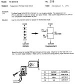
Forgive me for being in Mcgyver mode, , but I am just curious if this would work:

With the resistor values shown, voltage drop would be about 2.5V, at 150uA that is, and one of the two can be adjusted for desired Vf. You could bolt the transistor to the heatsink, but would this be heat sensitive enough I don't know..
With the resistor values shown, voltage drop would be about 2.5V, at 150uA that is, and one of the two can be adjusted for desired Vf. You could bolt the transistor to the heatsink, but would this be heat sensitive enough I don't know..
Me neither, I just know that increasing R2 vs R1 will lower the voltage drop, and decreasing will do the opposite. Also, the voltage drop varies with the amount of current that flows through the circuit, but that is also the case with a diode string.Unfortunately I don't understand the calculations
I tried this in a simulator, and it worked there...
Last edited:
I wonder if there's a quad diode array in an SMT package that might be usable?The 1N4148's are gold-doped, resulting in a lower Vf, among other things.
General-purpose, non-doped diodes like the OA202 in Europe, and similar JEDEC parts have a higher Vf: 1N646 comes to mind, but it is largish, and also has a relatively low Vf. There are other types, in a smaller glass case, but I don't have them in mind.
Other options are the BE junction of a small-signal transistor, but they tend to be more bulky (leave C open), a varicap diode, a high voltage avalanche diode (>47V)
2.518V at the right side wich has the original diode.
2.665V at the left side with the 4x 1n4148 diodes.
2.665V at the left side with the 4x 1n4148 diodes.
I mean the current through them, not the voltage across. You would need to put your multimeter in series with the diodes and measure (mili)amperes.
If I put 4x 1n4148 diodes in series in my simulator, I have to run about 5 miliamps through them to get 2.665 voltage drop.
With 5 miliamps, to get 2.518V drop from the 'rubber diode' circuit I posted above, the value for R1 should be 4.7k and R2 1.65k.
If I put 4x 1n4148 diodes in series in my simulator, I have to run about 5 miliamps through them to get 2.665 voltage drop.
With 5 miliamps, to get 2.518V drop from the 'rubber diode' circuit I posted above, the value for R1 should be 4.7k and R2 1.65k.
Last edited:
Sorry, but that is the same way as i measured the voltages, isn't it? But i don't get any readings in amperes... my meter does not red less than 25ma.. or am i doing something wrong? Voltages over cathode and anode...
To measure the current, you would have to disconnect one side of the diode string, and put one probe at the loose end of the diode string, other probe where the string was connected. That is in series. The voltage measurements are in parallel. If in doubt, google it 😉
Oh, yes sorry. In series ofcourse! I know that, but sometimes.... 😵
I have to desolder. I will do that tomorrow. Thank you for your input by now!
I have to desolder. I will do that tomorrow. Thank you for your input by now!
Hmm, something did not go well 😳 Desoldered the Cathode side of the diode and put my multimeter (ampere mode) in series. Probably did something wrong. Dimbulb goes very bright when turning on the amplifier... I'll have to figure that out.
The trick of the Vbe multiplier is that the base current Ib does not pull to much current from the current through the base-emitter resistor Irbe, while at the same time this current approximates the current through the collector-base resistor Ircb, which should not pull to much current from the actual collector current Ic.@ #24: but I am just curious if this would work:
In a mathematical form: Ib << Irbe << Ic.
Knowing that Ic = β * Ib, the optimum can be found by: Irbe = Ic / √β (the 'sweet spot')
Thus, Rbe ≈ Vbe / ( Ic / √β): Rbe = √β*Vbe / Ic
This is viable for any application of the Vbe multiplier.
I just liked to build this with the components in schematic, but results seem quite different. See attachment 😉Forgive me for being in Mcgyver mode, , but I am just curious if this would work:
View attachment 1286066
With the resistor values shown, voltage drop would be about 2.5V, at 150uA that is, and one of the two can be adjusted for desired Vf. You could bolt the transistor to the heatsink, but would this be heat sensitive enough I don't know..
Attachments
Or get a dual diode in TO-220. You can get them with the diodes connected in series. Then just bolt the TO-220 to the heat sink with appropriate mounting hardware/pads and/or thermal goop and you'll be set.Also, no matter if you end up with 3 or 4 x 1N4148, place them afterwords on the heatsink and cover them with thermal paste,
to get them to function as close as the originals.
- Home
- Amplifiers
- Solid State
- Unknown diode