Exactly where the base current Ib has a substantial draw too from Ircb, increasing the total Vce (5.4 instead of the expected 4.2).but results seem quite different

The schematic in post #24 works with about 150uA current, but if more current is running you need different resistors. Your tester runs 1250uA through the circuit, so you get a different result. With higher currents, you need to use lower value resistors, like in post #31.I just liked to build this with the components in schematic, but results seem quite different.
This is why I wanted to know how much current runs in your diode string when the amp is working. I am sorry you fried a transistor, I hope it was not caused by just measuring the current.. but I can't see why.
The 3.8v drop you show in post#39 is actually to be expected when running 1250uA with 150k and 47k, I get a similar value from the simulator.
Thanks citizen124032 for posting the formulas. I think suitable values for the resistors in this case, assuming a few miliamps of current, would be 4.7k for R1 and about 1650 ohms for R2.
Last edited:
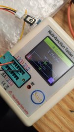
BD139 and 4.7k for R1 / 1.5k for R2. See test attachment with multimeter. Think i'm going to solder this one, seems to get closer and in circuit it's less current.
(I'll replace the output transistor. Not sure why it shortend. Happens often when I'm messing around 😆 )
(I'll replace the output transistor. Not sure why it shortend. Happens often when I'm messing around 😆 )
Attachments
Last edited:
Yes, but these BD's with washer fit really nice to the "heatsink".... just a plate of alluminium.The BD139 is not exactly known for high beta. Just saying. Maybe try a BC547C with a clamp holding it onto the heat sink instead.
Tom
I hope it works! you can connect a 150 ohm resistor, if you have one, in series with the 1.5k to get closer to 1650 ohm.
... times the initial Vbe voltage...5.4 instead of the expected 4.2
I was just shorting things here.
Three ranges are available, crap, messy & owkae, being (where's that datasheet?) 80-110-160, or close to.The BD139 is not exactly known for high beta.
So these are divided in 'range blocks' of some 30% (subprime selling comes in mind now...).
The 'best' range, the 160 series (BD139-6) has a beta-flex range of some 25% on its own...
Thanks citizen124032 for posting the formulas.
... which leads to the the ultimate rubber formula's:
Rbe = √β*Vbe / Ic
And the desired bias or zener voltage of this Vbe multiplier compound:
Vz = { ( Rcb + Rbe) / Rbe } * Vbe
reducing Rce to:
Rce = { (Vce / Vbe) - 1 } * Rbe
With any given bipolar junction transfer resistor ("bjt"), and considering the beta-range of the series, silver banded resistors are good enough.
Assuming a regular bias Vbe multiplier circuit running @ say 5mA, the BD139-6 requires:
Rbe = (√160 * 0.7) / 5mA = 1k77 -> 1k8
and a bias voltage four times the Vbe:
Rce = { (2.8 / 0.7) - 1 } * 1k8 = -> 5k4 (from the 1k8!) -> 4k7 + 1k0 adjustable resistor (@700Ω @ calculated optimum).
Apply to the actual bias current if the semiconductor involved is suitable for the application: 4k7 <> 5k1 <> 5k6.
Civilisation is granted by math only, a sublime greek heratige.
(Odysseus is my hero)
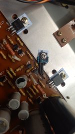
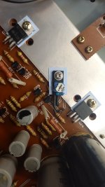
I placed a 100 ohm resistor in series + the 1.5k resistor for R2. It seems to be working! Tested the unit and the base voltage of the output transistors has now lowered from 0.68V to 0.65V. Still a bit high, but there is result 😀
If i raise the resistance of R2 a bit more to 1650 ohms as you suggested , will it decrease the base voltage of the output resistors? (I really don't get the math etc. etc) Thank you!
If i raise the resistance of R2 a bit more to 1650 ohms as you suggested , will it decrease the base voltage of the output resistors? (I really don't get the math etc. etc) Thank you!
Attachments
... times the initial Vbe voltage...
I was just shorting things here.
Three ranges are available, crap, messy & owkae, being (where's that datasheet?) 80-110-160, or close to.
So these are divided in 'range blocks' of some 30% (subprime selling comes in mind now...).
The 'best' range, the 160 series (BD139-6) has a beta-flex range of some 25% on its own...
... which leads to the the ultimate rubber formula's:
Rbe = √β*Vbe / Ic
And the desired bias or zener voltage of this Vbe multiplier compound:
Vz = { ( Rcb + Rbe) / Rbe } * Vbe
reducing Rce to:
Rce = { (Vce / Vbe) - 1 } * Rbe
With any given bipolar junction transfer resistor ("bjt"), and considering the beta-range of the series, silver banded resistors are good enough.
Assuming a regular bias Vbe multiplier circuit running @ say 5mA, the BD139-6 requires:
Rbe = (√160 * 0.7) / 5mA = 1k77 -> 1k8
and a bias voltage four times the Vbe:
Rce = { (2.8 / 0.7) - 1 } * 1k8 = -> 5k4 (from the 1k8!) -> 4k7 + 1k0 adjustable resistor (@700Ω @ calculated optimum).
Apply to the actual bias current if the semiconductor involved is suitable for the application: 4k7 <> 5k1 <> 5k6.
Civilisation is granted by math only, a sublime greek heratige.
(Odysseus is my hero)
Wow, I wish I could understand all this. 😳 😵 .... But really interesting to interpret it a bit.
Time & patience.But really interesting to interpret it a bit.
Get yourself saved from that shelve you're fixed upon tio.
Only dead fish go with the flow.
Yes, if you raise R2 it decreases the forward voltage of the circuit. Great that it seems to work in practice! now I hope it tracks the temperature well enough, we don't want any more fried transistors..If i raise the resistance of R2 a bit more to 1650 ohms as you suggested , will it decrease the base voltage of the output resistors?
Also fun to see how the elegant greek math approach gives about the same results for the R values.
And I have to say, th BD139 with the resistors soldered around it, it looks quite professional!
I love developing these kinds of ideas. That's why it's nice that these forums exist. People with the knowledge and I have handy hands! I'm going to look for 150 ohm resistors for R2. Must have them somewhere. Yesterday I only had 100 ohms available. Thanks for all the contributions!🙏
- Home
- Amplifiers
- Solid State
- Unknown diode