Hello everyone. I hope this is the right place to post this. I recently obtained a tube amplifier from an estate and I don't know anything about it. It doesn't appear to be a commercial product or a kit. Has anyone seen an amplifier like this?
Attachments
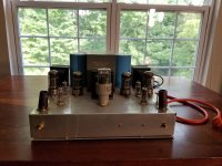
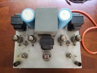
Looks like a home brew stereo P-P 6080 tube Amp. Would be quite interesting to see any schematic for it, or at least what tubes it is using and the output xfmr type (outmost xfmrs). Looks like the power xfmr has the winding voltages printed on it, helpful to know.
There is a thread recently looking for 6080/6AS7 tube Amps.
There is a thread recently looking for 6080/6AS7 tube Amps.
Last edited:
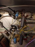
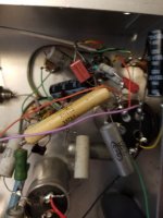
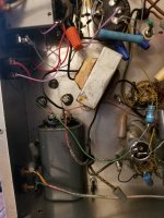
Don't plug it in, and leave for a day for the caps to discharge, but if you could take a photo of the insides (it looks like a panel would come off the underside). I agree it looks like a push pull stereo amp. Careful as the pins and tubes can break but an inside photo would allow us to trace the circuit out.

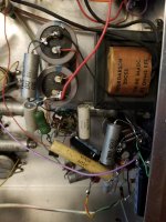
I noted the IDs of the tubes, transformer, and capacitors -
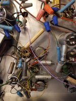
The center tube is a Raytheon JAN 5R4WGB, the four large tubes along the center rear are Tung Sol 6080WB.
The two small tubes at the front corners are Telefunken EEC81 51192
The large transformer is General Applied Science Laboratories PSG-1-P-0021
The three smaller transformers have no markings.
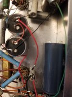
The capacitors are Mallory 1900 MFD 450 VDC CGS192T450X5L3PH.
The remaining four small tubes appear to be 12BH7A 4643, but that isn't clear to me since some of the lettering has faded.
The center tube is a Raytheon JAN 5R4WGB, the four large tubes along the center rear are Tung Sol 6080WB.
The two small tubes at the front corners are Telefunken EEC81 51192
The large transformer is General Applied Science Laboratories PSG-1-P-0021
The three smaller transformers have no markings.
The capacitors are Mallory 1900 MFD 450 VDC CGS192T450X5L3PH.
The remaining four small tubes appear to be 12BH7A 4643, but that isn't clear to me since some of the lettering has faded.
Maybe something like this, except using 12BH7 tubes in place of the 12AU7 and 6SN7.
https://www.angelfire.com/electronic/funwithtubes/Triode_Power_Amplifier.html
6.5% distortion at 12.5 Watts, 4% at 5 Watts. The 400V B+ exceeds the 250V B+ max 6080 tube ratings however?
The winding voltages on the central power xfmr should give some clues.
It seems that these mu 2 tubes are difficult to get good low distortion results, partly from the difficult driver stage and partly from the non-linear 6080.
JHStewart9 has a P-P 6080 amplifier design using a bootstrapped 6SN7 driver stage, 400V B+, and fewer tubes. (not requiring a separate 500V B++ for the driver stage as in the above)
https://www.diyaudio.com/community/threads/novel-driver-for-6as7.384337/#post-6974040
0.72% dist at 10 Watt
Last edited:
try this- to read faded markings. Place the tube in the freezer for a few minutes, remove from freezer then lightly breathe / blow on the tube. Markings might show up.
or use a magnifying light.

or use a magnifying light.
Last edited:
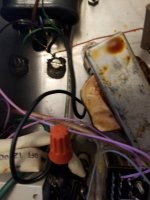
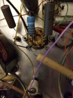
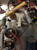
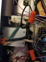
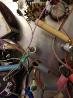
Here are the pictures. At this point, I can either start disassembling and documenting the amplifier, or I can sell this to someone with a lot more time and knowledge of electrical engineering.

Attachments
-
 20220701_200102.jpg357.4 KB · Views: 118
 -
 20220701_200109.jpg277.7 KB · Views: 113
 -
 20220701_200115.jpg295.6 KB · Views: 106
 -
 20220701_200121.jpg396.5 KB · Views: 107
 -
 20220701_200131.jpg318.7 KB · Views: 110
 -
 20220701_200138.jpg284.7 KB · Views: 109
 -
 20220701_200146.jpg360 KB · Views: 106
 -
 20220701_200151.jpg323.4 KB · Views: 108
 -
 20220701_200158.jpg386.6 KB · Views: 119
 -
 20220701_200201.jpg429.1 KB · Views: 122
 -
 20220701_200213.jpg377.9 KB · Views: 113
These are taken upper-left to lower-right in three rows, left to right. Maybe I can stitch the images together to made one image.
Cringe. It's definitely home brew, and perhaps the constructor was drinking some while putting it together.
It looks like it was a prototype with many changed connections and updates as the circuit was refined. Personally, I would rewire it and clean up the layout and connections, remove wire nuts and hanging wires, and components. I would remove the old electrolytic capacitors and update them to MKP4.
some schematics 6080 / 6as7
http://www5a.biglobe.ne.jp/jh2clv/6080schematic.htm

?

https://www.angelfire.com/electronic/funwithtubes/Triode_Power_Amplifier.html
following page has some 6as7, 6080 pp
http://lilienthalengineering.com/100-amplifiers-chapter-1/100-amplifiers-part-2-1945-54
http://www5a.biglobe.ne.jp/jh2clv/6080schematic.htm
?
https://www.angelfire.com/electronic/funwithtubes/Triode_Power_Amplifier.html
following page has some 6as7, 6080 pp
http://lilienthalengineering.com/100-amplifiers-chapter-1/100-amplifiers-part-2-1945-54
Many thanks to everyone who responded. I am currently disassembling, documenting, and cleaning the amplifier. I'll upload pictures and notes as I go.
- Home
- Amplifiers
- Tubes / Valves
- Unknown Amplifier