After 18 years challenging myself, learning from you and sharing nice projects I will leave this forum.
Also because being bullied and get physical threads without support of the moderators for the last 18 years.
See you all on the next forum.
R.I.P by mod.
Also because being bullied and get physical threads without support of the moderators for the last 18 years.
See you all on the next forum.
R.I.P by mod.
Last edited:

"What will be the difference in sound?"
No difference in my experience, especially in the case of class D.
No difference in my experience, especially in the case of class D.
I don’t know if you will hear any difference.
But you will have the option of separated grounds.
Sometimes it is useful.
But you will have the option of separated grounds.
Sometimes it is useful.
Eval2 has no opamp socket and not all off the bypass options.
Cost of Eval2 is high. DIY Board shall cost about €50. And has more options.
Cost of Eval2 is high. DIY Board shall cost about €50. And has more options.
Modules are from ALI express or Ebay.
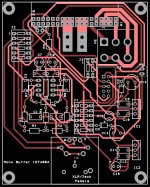
I had some difficulties with the design of the stereo PCB. I could not use the track size i want for the power nets because of to less space. So i have made a mono version. Size 80 x 100mm.
If there are no comments i will generate the gerberfiles and order the PCB's at JLCpcb.
I had some difficulties with the design of the stereo PCB. I could not use the track size i want for the power nets because of to less space. So i have made a mono version. Size 80 x 100mm.
If there are no comments i will generate the gerberfiles and order the PCB's at JLCpcb.
Attachments
Thanks for the links.
For me also the reason to hav the posibillity to bypass the onboard opamp and use a extern preamp.
I have a tube headphone amp and a lme49600 preamp i like to try with the 1ET400A.
For me also the reason to hav the posibillity to bypass the onboard opamp and use a extern preamp.
I have a tube headphone amp and a lme49600 preamp i like to try with the 1ET400A.
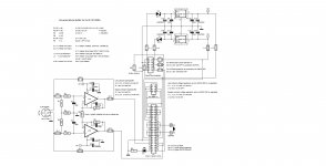
Error on PCB layout???
Koifarm,
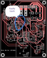
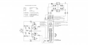
I am very interested in this project and have been following it closely. To that end I found myself studying both your schematic and PCB layout. Not be 'nit picking' (okay I admit it, I am nit picking) but I noticed that you have swapped the exit connections on J1-5 and J1-6. It should still work but we should note that the functions controlled by the switches have swapped, that is whatever was controlled by J1-5 is now on J1-6 and what was on J1-6 is now on J15.
Have you changed the PCB layout since the one that you posted? Do you plan to make the Gerbers available? Thank you for sharing your hard work and for tolerating nosy buggers such as myself.
Koifarm,
I am very interested in this project and have been following it closely. To that end I found myself studying both your schematic and PCB layout. Not be 'nit picking' (okay I admit it, I am nit picking) but I noticed that you have swapped the exit connections on J1-5 and J1-6. It should still work but we should note that the functions controlled by the switches have swapped, that is whatever was controlled by J1-5 is now on J1-6 and what was on J1-6 is now on J15.
Have you changed the PCB layout since the one that you posted? Do you plan to make the Gerbers available? Thank you for sharing your hard work and for tolerating nosy buggers such as myself.
Thanks Carl for your reply.
I did not change the PCB and have ordered 10pieces.(have some to share)
After testing i will publish the gerbers and drawings as-build.
Ronny
I did not change the PCB and have ordered 10pieces.(have some to share)
After testing i will publish the gerbers and drawings as-build.
Ronny
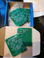
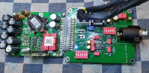
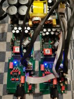
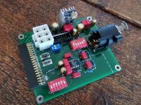
Today i build two buffers. There was a faulty track on the pcb. I did it myself in the design. I solved it on the prototype PCB. After that the buffer work as expected.
The Hypex smps start the Purifi amps with a little delay and off there is also no strange sounds. Dc/fatal error signal also works between smps and amp.
Bypassing the opamp buffer with the dipswitch also function great.
I have not tested the onboard regulators because i must wait for the negative supply regulators(lt3094). But bypassing them with the dipswiches and use smps buffersupply function great.
Next view days i will listen to the amps and make a casing. Further i modify the PCB without the faulty track and optimize some parts spacing. Then i publish the gerber files and schematic as-build.
Attachments
Last edited:
Koifarm,
I saw the faulty traces and convinced myself that was how you were handling grounds. I should have been more diligent and pursued it farther. Sorry about that. I could have saved you some frustration.
In any case I look forward to the fix.
I saw the faulty traces and convinced myself that was how you were handling grounds. I should have been more diligent and pursued it farther. Sorry about that. I could have saved you some frustration.
In any case I look forward to the fix.
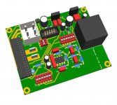
I have correct the faulty track. Give some components more space. And changed the holesize of the connectors to get a better fit. Updated the schematic as-build.And publish the gerber files.
Attachments

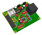
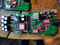
Today soldered the negative regulator on the board. Adjusted the voltages to + and - 12V.The positive regulator must have LM78XX pinout and the negative regulator must have LM79XX or LM337 pinout.
Also listen short to the Oracle 2 opamp. Sounds promising. Next building nice housing.
Also listen short to the Oracle 2 opamp. Sounds promising. Next building nice housing.
Attachments
Last edited:
- Home
- Amplifiers
- Class D
- Universal PCB for Purifi 1ET400A amps