However, it's important to remember that the closed-loop output impedance is the open-loop output impedance divided by (open loop gain * feedback factor) + 1. So closed-loop output impedance is almost always extremely low at audio frequencies.
Thanks for the follow-up! Good to know about the RRO and Miller compensation being responsible for that lower-frequency Zout plot.
For a single stage the closed loop Zout would definitely be as you wrote, but where I'm kind of not on the train is what happens with the Zout of the "inner" looped op amp. So in this case an OPA2140 driving an OPA1622 (or in one of my other projects an OPA140 driving a LME49600). The ouput of that OPA1622 (or OPA49600) will definitely be the formula you wrote due to the negative feedback. But what about the Zout of that "inner" OPA2140 (or OPA140). Will that outer negative feedback loop around the OPA2140 + OPA1622 pair cause that Zout to adhere to the same formula?
I've wondered if it would take an "inner" feedback loop, such as the "multiloop" configurations that used to be popular, here at Tangent't site:
http://tangentsoft.net/audio/pimeta2/misc/sch-2.01.pdf (opens PDF)
To cause that "inner" op amp Zout to adhere to the formula. Any thoughts here are greatly appreciated! 🙂
Last edited:
Thanks for the follow-up! Good to know about the RRO and Miller compensation being responsible for that lower-frequency Zout plot.
For a single stage the closed loop Zout would definitely be as you wrote, but where I'm kind of not on the train is what happens with the Zout of the "inner" looped op amp. So in this case an OPA2140 driving an OPA1622 (or in one of my other projects an OPA140 driving a LME49600). The ouput of that OPA1622 (or OPA49600) will definitely be the formula you wrote due to the negative feedback. But what about the Zout of that "inner" OPA2140 (or OPA140). Will that outer negative feedback loop around the OPA2140 + OPA1622 pair cause that Zout to adhere to the same formula?
I've wondered if it would take an "inner" feedback loop, such as the "multiloop" configurations that used to be popular, here at Tangent't site:
http://tangentsoft.net/audio/pimeta2/misc/sch-2.01.pdf (opens PDF)
To cause that "inner" op amp Zout to adhere to the formula. Any thoughts here are greatly appreciated! 🙂
Ah OK, didn't realize we were talking about a composite amplifier circuit. The "global" feedback loop reduces the output impedance of the total circuit. If the OPA2140 doesn't have a local loop around it, then the output impedance "seen" by the OPA1622 will be the open loop output impedance of the OPA2140.
Ah OK, didn't realize we were talking about a composite amplifier circuit. The "global" feedback loop reduces the output impedance of the total circuit. If the OPA2140 doesn't have a local loop around it, then the output impedance "seen" by the OPA1622 will be the open loop output impedance of the OPA2140.
johnc124 - Interesting! A *big* thanks, I've been puzzling over that for a couple of years now. So as far as the (looped) OPA1622 is concerned (or LME49600 if that was the looped chip), at say 70Hz they would be looking back into an output Z of about 100 ohms with the OPA140/2410, or at 20Hz looking back into about 400R (from the OPA140 datasheet, graph 18).
So the big question: would it matter for audio? I'm guessing not. Take the 400R worst case (@20 Hz), the input capacitance of the OPA1622 appears to be about 1pF from the datasheet. So that would be a filter with a corner frequency of 400MHz, way way out of the audio band. I don't see an input capacitance in the LME49600 sheet, but the BUF634 is 8pF. I'm just assuming here that whatever the BUF634 does, the LME49600 is probably close behind. Assume National was hiding something - which seems to usually be the case when something standard is left off a datasheet! - and the 49600 input capacitance is nearly 3x at 20pF. That would be a corner at 20MHz, still way out of audio range.
A related thing I often see posted is 100R or more inserted between the output of the initial op amp in a loop (OPA2140 or OPA827 in the discussion here) and the buffer (OPA1622 or LME49600), which would add resistance to the calculations above. I've discovered one reason for this added resistor myself, the BUF634/LME49600 has input protection diodes that apparently (datasheet) can become forward biased when the output of the BUF634 is shorted, as in every time a TRS jack it is powering is inserted or removed. So that resistor is needed to limit driving current if the driving chip is not short circuit protected. While searching for that multiloop link above I found another interesting reason for the resistor that jcx had posted two years ago, that the BUF634 can have a region of negative input Z:
http://www.diyaudio.com/forums/head...ltiloop-amp-output-impedance.html#post3993713
jcx is usually right about these things! So that series resistor would also be for isolation. Does the OPA1622 ever have negative input impedance? I'm guessing not since you (wisely! IMHO) left off input bias current cancellation.
OlegSh - sorry for jumping in your thread here, I'll shut up. 🙂 Hopefully this info is helpful for your board and it certainly is answering a bunch of questions I've had lingering for a long time. Thanks!
Last edited:
There is no increased distortion. With regards to Figure 37, that was measured with the amplifier in a buffer configuration (not the distortion gain configuration shown in Figure 35) which means that the noise floor of the audio analyzer (APx555) limits the measurement capability. But also remember the "N" portion of THD+N, you will always have an increased noise due to the source resistor itself. In this case however, the noise floor of the audio analyzer is the major contributing factor.
Thanks for the explanation, John! Now I can continue with my project🙂
OlegSh - sorry for jumping in your thread here, I'll shut up. 🙂 Hopefully this info is helpful for your board and it certainly is answering a bunch of questions I've had lingering for a long time. Thanks!
No problem, agdr! Please feel free to discuss those issues in this thread, I learn a lot from your conversation.
I am assembling a buffer using OPA2140 to go after the volume pot and before the OPA1622 board and am stumbled upon a question, how to select a resistor which goes in series with the non-inverting input of the op-amp? I’ve seen values in the range from 0 to 1000s Ohms. Is there a way to calculate the value of this resistor or at least to reasonably estimate it?
Regards,
Oleg
Regards,
Oleg
As a lower value makes for lower noise you would like it to go to 0. But that will make it hard for the driving stage so you need to up it because of this. Now, choose the poison 🙂
//
//
I guess I wasn't clear with my question. I am asking about the resistor in series with the input, not the one to ground.
Yes, but the discussion in post 160 is mostly about varying resistance stemming from the volume pot. Here I am asking about the fixed resistor which, if I am not mistaken, sometimes called gate stopper or so...
I ment the series R in #167. agdr talks about it in #163 - he mentions "So that resistor is needed to limit driving current if the driving chip is not short circuit protected."
//
//
Yes, I am talking about that 100 Ohm resistor that agdr talks in post #163. I just want to know how this resistor is calculated or at least estimated. I see people sometimes omit this resistor or use something which looks like a random value between 100s and 1000s Ohms.
But thanks anyways for looking at my thread🙂
But thanks anyways for looking at my thread🙂
Just to clarify, I am talking about resistor R2L on Fig. 2 from ESP's project 88 page.
Rod Elliot is using that resistor in combination with the input capacitance of the op amp (relatively high on the JFET-input OPA2134) to form an RC lowpass filter for EMI immunity.
Another purpose is to match the source impedances presented to both op amp inputs which can reduce common-mode distortion effects from the varying input impedance of the op amp. This type of distortion is worst in older JFET input op amps (like the OPA2134), but the OPA2140 family does not show this behavior.
Thanks a lot for the explanation, John! I understood the rationale behind R2L resistor from Rod Elliot's project 88 article, I also learned about the impedance matching from your and Sergey88 posts a while ago. I just have been a bit confused by what seemed like random values I saw in various implementations.
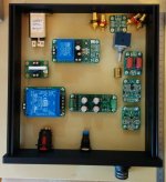
I am slowly putting together various bits which should become a stand alone head-amp one day. Attached is the preliminary layout inside of chassis. The ON/OFF will be operated via the push button with standby circuit. It will automatically switch the input to "path through" when OFF and will connect it to the volume pot when ON. It will also turn ON/OFF the head amp's power supply by a relay.
Attachments
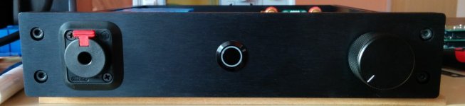
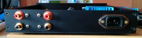
I have finally done all the drilling and mounting of parts inside of chassis. Now waiting for the molex crimping tool to complete the cabling. It should be in my hands within a week. Also bought myself USB audio interface (Focusrite Scarlett 2i2 2nd gen) for quick measurements, new digital soldering station and a lot of drilling hardware for the large diameter holes. I must say it becomes progressively more expensive hobby when one has to buy all the tools for it...
Regards,
Oleg
Regards,
Oleg
Attachments

Looking really good!
I will be interested to hear your impressions of the Focusrite Scarlett 2i2 as well. I've been interested in those as well.
I will be interested to hear your impressions of the Focusrite Scarlett 2i2 as well. I've been interested in those as well.
- Home
- Amplifiers
- Headphone Systems
- Universal buffer/headamp based on OPA1622