The cables I used are the TRS to 2xRCA stereo cable for the 2i2 output -> HA input, and TRS stereo to 2xTS cable for the HA output -> 2i2 input.
I have finally finished "The Wire" SE-SE by opc. I compared it to my OPA1622 head-amp and I can't tell them apart. They both sound really good. Measurements also do not show any significant distortion added by either of the head-amps to what the Focusrite 2i2 interface already has. So far I could only drive both amps by about 0.2Vrms signals (sweat spot of the 2i2) so I could not go above 1.25mW into 33 Ohm load for "The Wire" (gain of 1) and 5mW for OPA1622 (gain of 2). The distortion rise is really steep for the Focusrite 2i2 even if I add 1~2dB to the output signal level.
Anyways, I am happy with both amps... but I like mine better😉
Anyways, I am happy with both amps... but I like mine better😉
Attachments
Can I ask a dumb question. Why is it that you buffer after volume control? I can understand a buffer when you need more current or lower impedance. I tried googling to no avail.
The output impedance of a volume control (pot) is a) quite high and b) variable. The buffer eliminates both of these negatives. If you want to read a more detailed explanation, look for articles on "passive preamps" 🙂
Can I ask a dumb question. Why is it that you buffer after volume control? I can understand a buffer when you need more current or lower impedance. I tried googling to no avail.
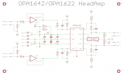
On top of what Nisbeth wrote I would add that OPA1622 is not a typical op-amp. According to johnc124, the designer of the chip, it has been designed to boost the output of the voltage output DAC (mostly in portable applications, thus the small package). This is reflected in the datasheet recommended schematic. Due to design decisions the input of the OPA1622 is very sensitive to HF interference as pointed earlier in this thread by Sergey888. I realized it in my own setup when I used initially higher input filter cutoff frequency than recommended in the datasheet and immediately heard cell phone "communication" every couple of minutes. Taking the values from the datasheet schematic fixed the problem. But here is also another problem. The cutoff frequency of this filter is rather low and if volume pot is placed just in front of it, the cutoff frequency will go up and down depending on the pot position acting as the tone control in some cases. Also OPA1622 has enormous input bias currents and if impedances on its inputs are not matched one should expect increased common mode distortion. Interestingly, Sergey888 showed that such distortion is not high even for 1k impedance imbalance, but it is still there. To solve all of these problems at once I just added a JFET input op-amp buffer in front of the OPA1622 to isolate it from the variable impedance of the volume pot and be able to use sufficient EMI filter without compromising the performance.
To minimize the wiring and reduce the head-amp overall footprint I'm currently working on the PCB with the buffer op-amp and the OPA1622 on one board. I am trying to keep board's size at minimum so there are some routing difficulties. I also plan to play a bit with DC-DC converters to see if they would be OK for the head-amp use. Then it may be possible to use a simple USB charger to power the head-amp. At the moment I plan to use assembled DC-DC converters like TDK-lambda. The question is how noisy they are...
Regards,
Oleg
DC-DC converter for OPA1622
My OPA1622 Headamp use a DC-DC converter for the neg supply. It's a charge pump operating at 2MHz, far from audio band. It provide very good results, at least for my hears as I do not have a FFT for now. It's a TI LM27661, it also embed a low noise LDO behind the charge pump in order to provide a clean supply. There's also the LM27662 which is a LM27761 plus a positive low noise LDO. The chip seems custom tailored for OPA1622.
Also on DIYA, EUVL did something with a LT chip, but I think it hasen’t the drive capability of LM27767x : near 200/250 mA max which fit the OPA1622 max output power.
On top of what Nisbeth wrote I would add that OPA1622 is not a typical op-amp. According to johnc124, the designer of the chip, it has been designed to boost the output of the voltage output DAC (mostly in portable applications, thus the small package). This is reflected in the datasheet recommended schematic. Due to design decisions the input of the OPA1622 is very sensitive to HF interference as pointed earlier in this thread by Sergey888. I realized it in my own setup when I used initially higher input filter cutoff frequency than recommended in the datasheet and immediately heard cell phone "communication" every couple of minutes. Taking the values from the datasheet schematic fixed the problem. But here is also another problem. The cutoff frequency of this filter is rather low and if volume pot is placed just in front of it, the cutoff frequency will go up and down depending on the pot position acting as the tone control in some cases. Also OPA1622 has enormous input bias currents and if impedances on its inputs are not matched one should expect increased common mode distortion. Interestingly, Sergey888 showed that such distortion is not high even for 1k impedance imbalance, but it is still there. To solve all of these problems at once I just added a JFET input op-amp buffer in front of the OPA1622 to isolate it from the variable impedance of the volume pot and be able to use sufficient EMI filter without compromising the performance.
To minimize the wiring and reduce the head-amp overall footprint I'm currently working on the PCB with the buffer op-amp and the OPA1622 on one board. I am trying to keep board's size at minimum so there are some routing difficulties. I also plan to play a bit with DC-DC converters to see if they would be OK for the head-amp use. Then it may be possible to use a simple USB charger to power the head-amp. At the moment I plan to use assembled DC-DC converters like TDK-lambda. The question is how noisy they are...
Regards,
Oleg
My OPA1622 Headamp use a DC-DC converter for the neg supply. It's a charge pump operating at 2MHz, far from audio band. It provide very good results, at least for my hears as I do not have a FFT for now. It's a TI LM27661, it also embed a low noise LDO behind the charge pump in order to provide a clean supply. There's also the LM27662 which is a LM27761 plus a positive low noise LDO. The chip seems custom tailored for OPA1622.
Also on DIYA, EUVL did something with a LT chip, but I think it hasen’t the drive capability of LM27767x : near 200/250 mA max which fit the OPA1622 max output power.
Hi AIM65,
I follow your thread with great interest. As for the DC-DC converters I have no experience with them so far. I noticed that you used it in your design and have been inspired to try. I have one +-15VDC TDK-lambda unit lying around for testing, but I may try the LM27767x instead, especially now knowing that there is already one working diy implementation🙂
Regards,
Oleg
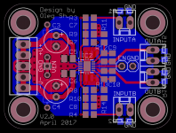
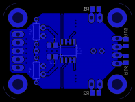
New PCB design
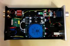
Attached is the "complete" head amp PCB design. It has the same form factor as the first version and allows feeding the head-amp directly by the volume pot without compromising performance. I placed OPA1642 right under OPA1622 in unity gain configuration. If gain other than 1 is needed it seems to be better to apply it to OPA1622 since the overall noise performance is better for the OPA1622. In addition I provided separate supply traces from the local reservoir capacitors and added dedicated local bypass caps for both ICs. So far the only concern that I have is the GND plane "bottleneck" between the bypass capacitors but I guess with the currents involved it should not be a problem. Also the way it is implemented allows to avoid supply and output return currents flowing under the signal traces and components.
Attached is the "complete" head amp PCB design. It has the same form factor as the first version and allows feeding the head-amp directly by the volume pot without compromising performance. I placed OPA1642 right under OPA1622 in unity gain configuration. If gain other than 1 is needed it seems to be better to apply it to OPA1622 since the overall noise performance is better for the OPA1622. In addition I provided separate supply traces from the local reservoir capacitors and added dedicated local bypass caps for both ICs. So far the only concern that I have is the GND plane "bottleneck" between the bypass capacitors but I guess with the currents involved it should not be a problem. Also the way it is implemented allows to avoid supply and output return currents flowing under the signal traces and components.
Attachments
Today I finally had the time to play with 6 Watt TDK-lambda isolated DC-DC converter (model: CC6-0512DF-E) as a possible power supply for the headamp. The converter requires 4.5~9VDC input and outputs +-12(+-15) VDC. I tried to measure the output ripple at ~180mA output current (both rails) with the scope and the ripple seems to be around ~300mVp-p at 50Mhz. I did not get stable waveform but the period and the amplitude were more or less clear. The datasheet indicates max. ripple of 120mVp-p which is much lower than what I measured. At 180mA output current the converter got warm to touch but not hot, which is good.
Now is the question, how to get rid of 300mV ripple at 50Mhz? If someone has an experience with such or similar DC-DC converters I would appreciate any pointers at how to use them properly and how to filter their outputs.
Oleg
Now is the question, how to get rid of 300mV ripple at 50Mhz? If someone has an experience with such or similar DC-DC converters I would appreciate any pointers at how to use them properly and how to filter their outputs.
Oleg
Today I finally had the time to play with 6 Watt TDK-lambda isolated DC-DC converter (model: CC6-0512DF-E) as a possible power supply for the headamp. The converter requires 4.5~9VDC input and outputs +-12(+-15) VDC. I tried to measure the output ripple at ~180mA output current (both rails) with the scope and the ripple seems to be around ~300mVp-p at 50Mhz. I did not get stable waveform but the period and the amplitude were more or less clear. The datasheet indicates max. ripple of 120mVp-p which is much lower than what I measured. At 180mA output current the converter got warm to touch but not hot, which is good.
Now is the question, how to get rid of 300mV ripple at 50Mhz? If someone has an experience with such or similar DC-DC converters I would appreciate any pointers at how to use them properly and how to filter their outputs.
Oleg
You could try an RC filter on both rail with 15 Ohms and 470uF. You’ll get near -120db @ 50MHz and a drop in R of 2,7V @180mA. But with RC you’ll certainly need regulators in order to get a clean supply; your TPSA49/30 boards will be fine for this.
If you do not want to use such post regulators, use LC instead of RC. With L=470uH and C=22uF you’ll get near -200dB @50MHz. For instance, L could be : EPCOS B82144A2474J000. Watch for ringing at power up or on strong load variation, but Q close to 0.6: it should be alright.
Last edited:
Hi AIM65,
If I understood it all right the problem with the frequencies in the range of tens of MHz is that they are not so easy to filter with conventional parts like ordinary electrolytic capacitor and an inductor. Both have their self-resonance frequencies much lower than the frequency that they should filter which renders them unsuitable for the job. For example the inductor you propose has self-resonance frequency of 1.5 MHz which means that above this frequency it starts to conduct due to its parasitic capacitance. In contrast the capacitor will behave more like an inductor above its self-resonance frequency.
I recently looked at the following filters which have high current capability and more than 40dB attenuation at 50 MHz. They are relatively small too but there are even smaller. I also plan to experiment with ferrite bids in the range of 1000kOhm impedance around 50~100MHz to see if I really need a filter as above or an ordinary ferrite bid would be enough.
The use of LDO regs is also a possibility but here only TPS7A47 can provide better attenuation than the filter. Even TPS7A33 which seems to be its complementary part has significantly lower PSRR in that region which is comparable to the filter. Also TPS7A30/49 parts have significant reduction of PSRR at 10MHz.
Regards,
Oleg
Check the ripple at the input to the converter as well. This also needs a common mode noise suppression capacitor (for each rail).
http://www.tdk-lambda.com/products/sps/catalog/eng/cc_e.pdf
http://www.tdk-lambda.com/products/sps/catalog/eng/cc_e.pdf
Hi SamAnytime,
I do consider to place a filter at both ends of the DC-DC converter. So far the problem is the need for a specifically designed PCB to play with SMD filter components. I'll sketch a prototype and will see how good it will work.
Regards,
Oleg
I do consider to place a filter at both ends of the DC-DC converter. So far the problem is the need for a specifically designed PCB to play with SMD filter components. I'll sketch a prototype and will see how good it will work.
Regards,
Oleg
50 MHz?
Oleg,
The description of the output voltage ripple measurements in the datasheet is surprising.
It’s written 'In 50 MHz' but not 'At 50 MHz'. Is the ripple measured within a 50MHz bandwidth or is it a 50 MHz ripple? Behind this question is the question of the operating frequency of the converter. 50MHz is VERY high, but not impossible I guess.
Before planning filter it may be useful to confirm the operating frequency, maybe 50MHz is the 9th or 11th harmonic…
I tried to measure the ripple with my scope at all possible horisintal and vertical scales. Even if I did not manage to have a stable waveform I saw a sliding/overlapping 50Mhz sinusoidal waveform copies of about 150mV amplitude. So I assume it is exactly 50Mhz. I may have misinterpreted the result and maybe I should try to trigger at the switching frequency to see the stable waveform but for now this is what I have. Note, that I measured the ripple before and after the output low pass LC filter made of 100uH inductor and 47uF electrolytic cap. The result was as if the filter was not there at all. This made me research further and thus I came to a conclusion about what filter should I look for. Turning the DC-DC power off removes the ripple so it is not a pick up by the scope probes of some other origin. I used an external AC-DC converter (USB charger) as well as battery (USB power bank) which most probably has built in DC-DC converter, and the result is the same. What I did not do is I did not measure the ripple at the input so far, but I doubt that 50MHz ripple is coming from the previous stage.
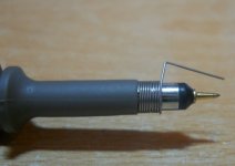
Probe
I’ve almost no HF experience, but when I’m making measurement within this range of frequency I’m usually very doubtful about what I see on oscilloscope screen. For example the GND grip of the oscilloscope probe is usually a great antenna which catch every close HF radiating source (SMPS, digital signal, etc…). It’s easy to dramatically improve the quality of your measurement with a simple accessory which provide a straight short Ground path to the measurement point.
I’ve almost no HF experience, but when I’m making measurement within this range of frequency I’m usually very doubtful about what I see on oscilloscope screen. For example the GND grip of the oscilloscope probe is usually a great antenna which catch every close HF radiating source (SMPS, digital signal, etc…). It’s easy to dramatically improve the quality of your measurement with a simple accessory which provide a straight short Ground path to the measurement point.
Attachments
- Home
- Amplifiers
- Headphone Systems
- Universal buffer/headamp based on OPA1622