@MarcelvdG I just tried from 44.1 to 192k. No change and I used a stopwatch this time. It is 21 seconds. Also I had written down numbers for the dac connected and disconnected. The disconnected numbers should have been 1.2-2.4mvdc for the trough and peak.
@simon7000 tried the 1k resistor. No change. And no stupid pills at least today!
The opa1612 and opa1656 are unity gain stable and I’m not seeing any sign of oscillation.
The thing that had me wondering is that at +-9vdc power the op amp temp goes up by16 deg c over ambient. When I go to +-15v supply it’s up 26 deg c. I thought that might be oscillation but I don't find any other indications.
Still don’t understand the dc offset oscillation coming directly from the dac( topping d10s) even when not connected to my buffer.
I was commenting on your statement :Aren't these circuits supposed to be shielded, surrounded by ground planes,having decoupled supplies, etc?...
In case you missed PMA's unexpected bad experience with sensitivity-of-opamps-to-air-coupled-em-fields-especially-of-the-lm4562-lme497x0-family.... i can only think about bad pcb practice, non compensated circuits or a possible impedance mismatch.I simply can't figure of any other possibility left.
Those images seem to show very low levels whichever way you look at it.shorted input but hard to tell ac harmonics from noise. However, taking the whole thing out of the aluminum chassis and thereby the signal grounds out of the chassis and picked up about .8 db in noise improvement.
If it's measurable then your circuit has a problem cause no AP can measure it with lm4562.
When an opamp is marginally stable it will work better with a gain of 3 to 10. To keep the system gain at unity an input resistor voltage divider is used to reduce the input by the same amount as the gain! Seems silly but does give better stability.
The inability to even measure distortion from so many high performance opamps is mentioned in their data sheets.

Ok...so pma complains about rf sensitivity of a 55mhz bandwidth op-amp with bipolar input...do i need to repeat myself or what? I use lm4562 in my Denon cd player made in 1991 and no rf is getting in as every healthy rule is obbeyed by its design.Call Denon design department and ask them what you can do then...
I knew that...its why i said it. I actually performed lm4562 measurements on AP system one and two in late 2015 while choosing a suitable op amp for an electrostatic headphones amp i had to make .I only touched that equipment for 5 weeks, but i saw the measurements with my own eyes...Luckily we( I wasn't alone in the project nor the analyzers were mine...) had to measure them in a circuit having about 2...500x gain using also a high voltage fet transistor, so we could see about 0.002% thd but we also had to make a separate differential probe with opa2132 to adapt the very high z output of the amp to 100kohm input impedance of the analyzers ...so we had the signals passing through two different circuits having their own problems thus we didn't have to measure lm4562 in unity gain circuits.We also tried ad797, opa1612, ne 5532, opa2134, njm4562 and a few others and we settled on opa1642 out of pure convenience, but all the op amps assessed delivered serious and reliable results and we had no problems with rf although we had the circuit supplied by a small smps and basically everything around us was supplied by smps...Everything goes down to how you prototype the pcb and shield the damn thing...simple things every designer does for 100 years with any low noise electronic circuit.The inability to even measure distortion from so many high performance opamps is mentioned in their data sheets.
View attachment 1025632
Last edited:
I know 🙂knew that...its why i said it.
That's why I backed it up with that image. You didn't cite any reference to back up what you said.
Thank you!I know 🙂
That's why I backed it up with that image. You didn't cite any reference to back up what you said.
I am using an opa1656 which is fet not bipolar and as pma suggests more stable.
The circuits /devices like dacs I’m interested in measuring are noisier than an opa1656. I’m just trying to get performance from this buffer as close as possible to directly connecting the dut to the e1da cosmos adc.
At this point it seems to be good down to -111db thd+n, basically equivalent to connecting the d10s directly to the e1da adc. I have verified the same with my Quantasylum qa402.
I will test it tomorow with an smsl su-9 dac which has much lower distortion at about -120db thd+n.
Last edited:
Sorry opa1632 was used for the differential probe which was bipolar input 180mhz...had no positive voltage gain so it needed some compensation ...you get it...
Tested on the smsl su-9 dac today and reached the boundary of this buffer circuit without going to a well designed printed circuit ( which I am not capable of).
Direct connect to the e1da dac I get thd of -125db and thd+n of -117.5db.
When I go through the buffer I get the following so at least I know the limits on noise now.

Direct connect to the e1da dac I get thd of -125db and thd+n of -117.5db.
When I go through the buffer I get the following so at least I know the limits on noise now.
Hi HearingAids,
Couple o' things . .
Cheers
edit: OK, too much good advice posted in the almost 3 days it took me to compose this 😱 please ignore if necessary . .
Couple o' things . .
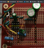
- in your pic in post #68, I don't see the recommended 0,1uF supply bypass capacitors
- maybe it's just me, but I wouldn't use NP electrolytics for supply bypassing
- forcing use of the pad-rows of the breadboard is causing some unwieldy ground returns -- dashed orange on the pic
Cheers
edit: OK, too much good advice posted in the almost 3 days it took me to compose this 😱 please ignore if necessary . .
Attachments
Last edited:
Thx for your time in reviewing it. I tried 100nf film and separately and combined with .01uf ceramics for higher frequencies. The best results I got were with the 10uf np. Maybe better with lower frequency issues. I don’t understand it.
Ok so on the ground bus. Run it on the solder side and connect to the perpendicular pad row where a ground is needed? Or am I misunderstanding?
Ok so on the ground bus. Run it on the solder side and connect to the perpendicular pad row where a ground is needed? Or am I misunderstanding?
You're welcome!
Yup, that's it exactly. Should reduce your ground inductance, which helps both stability and EMI susceptibility.
But it looks like you're already pretty much there -- minus 120 dBV S+N is pretty darn good! Congrats!
Cheers
Yup, that's it exactly. Should reduce your ground inductance, which helps both stability and EMI susceptibility.
But it looks like you're already pretty much there -- minus 120 dBV S+N is pretty darn good! Congrats!
Cheers
What about running power supply wires directly to the pad rows rather than down the + and - busses? Which is noisier, the power supply wire direct but obviously no longer twisted with it’s partners or the busses on that board?
You could get better common mode behavior by using one single regulator across the V-V+ and a virtual ground placed very close to your IC.It will help you when you get to the real world pcb using its own supply. Usually positive regulators don't have similar behavior while a virtual ground reffered to both rails obtained from one single regulator should improve the common mode noise.
Since you have only a single DIP8, I would skip the + and - busses on the Vero board. Each has only one connection once it gets past the local decoupling capacitors. Those can often be arranged neatly in two clumps, one near pin 4, and one near pin 8.
There is a difference between a chip that is stable at unity gain and a complete circuit.
If you have an oscilloscope that has a bandwidth of say 500 MHz you can probably see the oscillation. 100 MHz is often not enough. You might try building a simple RF probe. That is a small capacitor say 100 pF into a diode like a 1N4148 cathode with the anode being connected to circuit ground. You then look for DC across the diode.
There was an old paper that showed how to build a low pass filter by setting the gain high enough to hit the opamp corner frequency and then using an input attenuator to keep the system gain at unity. That is why even when using an opamp that is unity gain stable at at a gain above one and attenuating the signal can make the circuit stable!
I have a bunch of circuits using one of the TI new opamps and it turned out some of them were drawing 45-50 mA instead of the 28 mA (10 mA was for the power supply!) as expected. These circuits were being powered by a lower voltage rail than the lower current ones. It was a clear case of one of the chips oscillating. Changing one of the chips feedback bypass capacitor to a lower value solved the problem.
At some point I will have to re- characterize how the opamp phase gain behaves at lower voltage supplies. In the meantime I am going through the 400 or so units I have in stock that run at higher voltage to be sure none of them have that problem. So far none do. All units have previously passed a function test.
I suspect I will need to add a current draw test to the production process, just to be sure there is nothing else going on.
Note that the higher current draw units did pass the function test but most likely would have failed in the field.
@Rick PA Stadel I tried to follow your suggestions. As several had suggested also I went back to the 100nf bypass caps rather than the 10uf which did not improve things but didnt make them worse and since smaller left them in. I also took out the larger 220uf caps. I tightened up layout and ran the ground bus on the bottom side. Improved about another .5 or so db.


- Home
- Source & Line
- Analog Line Level
- Unity Gain Buffer Design Problem