john curl said:Without specific noise measurements on 510-9510 devices, we have nothing to compare to. I have done these measurements in the past, and the 1/f noise is not good, especially 2'd stage for phono stage preamps. . However for a power amp that is not equalized, I doubt that the A rated noise is effected much by a second stage that is 15 times away from the input.
You may be right, but at this point we are both just speculating. Since we are comparing topological approaches, as opposed to whether or not MOSFETs are used in the VAS, maybe I'll try a sim on a circuit using bipolar VAS. Maybe even the JC-3. What do you think?
Bob
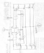
Bob, the JC-3 would not be the most appropriate circuit of this type to test for noise. The ideal, based on reality, would be the second stage of the SCP-2 designed about 20 years ago. It uses the comp diff Toshiba fet input stage, but it uses a cascode fet second stage, originally made of Hitachi mini mosfets (J76, K214) initially, but I DID have a noise problem with the mosfets and I swapped them with J72, and K147 devices as the bottom part of the cascode pair. That is a nearly optimum design for low noise. Someone around here most probably can put up the schematic.
So that people understand:
I generally don't design for super low noise in a power amp, because up to now, it has seemed to be less important than other factors, such as stage simplicity, or current drive for the output stage.
The complementary differential fet front end, itself, is low noise, however, and a resistive load is usually optimum for low noise operation. However, you must to have the second stage at an optimum operating point for lowest noise as well.
I have somewhere a circuit diagram said to be SCP, reverse engineered by someone I guess. Not me. I must check first.
RK
RK
It would appear that the schematic in the FIRST submission of the 'Inverting fet open-loop gain-stage' thread would work with a few small changes.
Bob Cordell said:
It is my understanding that Jim Bonjiorno conceived the complementary differential input pair while he was at Dynaco, put it into first commercial product in the SAE XXXIB in early 1973, and subsequently published it in PE as the Ampzilla in 1974.
Can you point to any commercial product that predates those?
Perhaps Charles Hansen can shed some light on this, as he seems very interested in audio history.
Is it possible that you are only laying claim to the implementation with JFETs that has the floating tails?
Bob
Bob Cordell said:
With circuits like these, it is certainly possible that multiple people came up with it, independently. But the first person who comes up with it independently and makes a commercial product out of it, or publishes a paper on it, is generally credited with it.
Many of us engineers, at one time or another, have had this sort of thing happen to them. That's life. You could invent Cold Fusion in your lab and not tell anybody about it, and you would not get credit for it. If you invent something and keep it under your hat, you don't get to claim it - that's just the way the world works.
SWTP was Dan Meyer, and as far as I know, he did not have any product with that circuit in it, at least in that time frame, and certainly not the Universal Tiger.
Cheers,
Bob
You mentioned Ampzilla, that brings back memories. You're correct that the Universal Tiger did not have a dual diff front end, however the Tigersaurus did:
SWTPC "Tigersaurus 250" 200W, Radio Electronics, December 1973
It is stated on this page that Ampzilla was designed in 1974:
http://www.ampzilla2000.com/Amp_History.html
I studied the schematics for the Ampzilla and Tigersaurus as a high school kid, when deciding what amp to build next, and found the Tigersaurus to be a cleaner design. It had a zener regulated front end, degeneration in the diff pair, and simple front end biasing.
Ampzilla had a lot of electrolytic caps around the diff amp because of the way it was biased as I recall.
Pete B.
john curl said:Bob, you will find the first 'in print' description of the complementary symmetry bipolar transistor input stage as an advertisement in ' The Audio Amateur' by SWTP in early 1972. Check it out. It is the Tiger .01.
Just saw this from you John, yes the .01 was dual diff also, I'll take your word for it that it was 1972.
Pete B.
I was there, you people are just guessing.
The real design is developed before the article is ever written. It is delayed because it is a trade secret, until it can be utilized. Many here can only rely on magazine articles, but I assure you that we had been making complementary differential input stages for years before anyone mentioned it in print. The designs were commericial, or custom, rather than consumer.
The real design is developed before the article is ever written. It is delayed because it is a trade secret, until it can be utilized. Many here can only rely on magazine articles, but I assure you that we had been making complementary differential input stages for years before anyone mentioned it in print. The designs were commericial, or custom, rather than consumer.
john curl said:I was there, you people are just guessing.
The real design is developed before the article is ever written. It is delayed because it is a trade secret, until it can be utilized. Many here can only rely on magazine articles, but I assure you that we had been making complementary differential input stages for years before anyone mentioned it in print. The designs were commericial, or custom, rather than consumer.
Jim Bongiorno or Dan Meyer could say the same thing. What specific commercial design did you put the complementary input stage into before Dan or Jim published it?
Bob
Bob, I don't like your tone, but I did expect it from someone.
This is my history of the complementary differential:
Back in 1968, I was experimenting on making the best amp possible to drive my single Klipschorn. With a nominal 8 ohm impedance, and 104 SPL/ watt, a 10W amp was enough, and I made it on a single piece of vector board, with a commercial dual TO-3 heatsink attached on one end. I still have this little amp.
I had access to some of the finest devices in the industry. Ampex also made video, instrumentation, and custom researched recorders, such as a digital recorder and a laser beam writing on film recorder.
We had a huge parts store to design with. The real problem was that some materials at the time were exotic and expensive. Too expensive to put into mass produced audio equipment. Still, I had access to matched complementary pairs of bipolar transistors and complementary power transistors.
I had this idea of the complementary differential in order to better drive the second stage, instead of a single ended driver, that was common at the time. I built it, measured it, and put it on the K-horn. I was very happy with the result, and by fortunate circumstance, Mark Levinson came by my house in order to copy a tape. He heard the amp in action, and although I did not see him for another 5 years, he remembered the sound of the amp, and he hired me on the spot to design future products in 1973, when we happened to meet at an AES convention.
I offered this design to the Ampex audio department in 1968, but they were not interested. Too expensive, too exotic.
However, in 1969, I moved down the hall to the reseach department to make an exotic video recorder. My specialty was servos, NOT video electronics. However, I noted that if we could make a truly differential out, power amp, we could improve power supply utilization, and I offered to make a large balanced bridge power amp. Here is where the complementary differential came in again and we made a large amp that was both differential in and differential out with the complementary differential input stage.
Still, they found the design confusing and rather complex, so they dropped it as well.
Next, in 1970, I went to work for Alembic Inc, in San Francisco. They make custom musical instruments and electronics for rock musicians. I then started making a series of amp prototypes with the complementary differential input stage, as well as line drivers for telephone line hookup to radio stations, etc.
In 1972, I was in London, and I met Bob Stuart at an AES lecture by Baxandall. He invited me to a party at his house. At the party, we discussed amp design, and I gave him the complementary differential input stage on a napkin, in order to help him out.
I already knew that the complementary differential concept was out, in print, as an advertisement on the back of 'The Audio Amateur' by SWTP, and I had used it for 4 years up to this time. Therefore the secret was out, and it was pointless to keep it to myself any further. I was surprised when he tried to patent the concept within the year, but then that is why I kept it quiet in the first place, except I was more worried about Marantz or some American firm taking the idea and running with it.
Borgornio came later, and I was specifically and completely told by Dan Meyer that HE first showed the concept to Borgornio, when they met.
Independently, Jon Iverson, of ElectroResearch, used the complementary differential from the late 60's as well. He might have proceeded me, but I could never get a fixed date from him. Now there was a brilliant designer!
To complete the timeline: In late 1972, I was again hired by Alembic to make the electronics for a new sound system for the Grateful Dead. By now, I had converted to complementary differential j-fet inputs. By June 1973, I had a transconductance line amp design completed, and when I started to work with Mark Levinson, I asked him if he would like to make this circuit as a module, for the Grateful Dead. He made a run of these modules for the GD, and then decided to make a consumer preamp, using this design as the line amp. This became the JC-2.
Mr. Cordell, I found a good supply of 2n5564, 65, 66 fets at Mouser. These are Vishey devices. Be prepared to pay as much as $15US for them though.
Thanks, DonS
Thanks, DonS
That is the problem with 2N5564-6. They are really made for the military, and cost big bucks. Bob was also referring to the NPD5564-6, that 'was' much cheaper.
Don S said:Mr. Cordell, I found a good supply of 2n5564, 65, 66 fets at Mouser. These are Vishey devices. Be prepared to pay as much as $15US for them though.
Thanks, DonS
Hi Don,
Unfortunately, the 2N5564 is not the same as the National NPD5564. The 2N5564 is actually composed of two matched JFETs in one package, whereas the NPD5564 is a single monolithic die.
Cheers,
Bob
Bob Cordell said:
Hi Don,
Unfortunately, the 2N5564 is not the same as the National NPD5564. The 2N5564 is actually composed of two matched JFETs in one package, whereas the NPD5564 is a single monolithic die.
Cheers,
Bob
Thank you Mr. Cordell. That is good to know. I was going to use the 2n5565 as a replacement for a NPD5565 in an old amp I have. I'm glad I didn't!
Thanks, Don
Bob Cordell said:
Hi Don,
Unfortunately, the 2N5564 is not the same as the National NPD5564. The 2N5564 is actually composed of two matched JFETs in one package, whereas the NPD5564 is a single monolithic die.
Cheers,
Bob
Bob,
Which version is the better in your opinion, matched or dual monolithic?
QSerraTico_Tico said:
Bob,
Which version is the better in your opinion, matched or dual monolithic?
I would prefer the dual monolithic devices, but that is not based on comparative experience. I have never used a matched-pair JFET device like the Vishay 2N5564.
If the dual monlithic devices are made in a process that is as good as the process that the discretes are made with, they will tend to be at least as good. There is one caveat, however. The dual monolithic devices share a common substrate, so there is a very small amount of possible inter-device capacitance. Some circuits might be degraded by this. However, in a typical differential pair arrangement at audio and low-RF applications, I don't think this will be an issue.
Cheers,
Bob
john curl said:To complete the timeline: In late 1972, I was again hired by Alembic to make the electronics for a new sound system for the Grateful Dead. By now, I had converted to complementary differential j-fet inputs. By June 1973, I had a transconductance line amp design completed, and when I started to work with Mark Levinson, I asked him if he would like to make this circuit as a module, for the Grateful Dead. He made a run of these modules for the GD, and then decided to make a consumer preamp, using this design as the line amp. This became the JC-2.
John, when you mention your work for the Grateful Dead in this time period, does this mean that these precursors of the JC-2 was what was used in the Wall of Sound? I am very interested in how this design was incorporated into the Live Sound environment.
- Status
- Not open for further replies.
- Home
- Amplifiers
- Solid State
- Unipolar vs complementary input stage