Sorry,
I did not try and create my own schematic from that picture.
Nor did I trace the wires out to see where they were connected.
Lazy me.
So, there are no potentiometers across the filaments, with the wiper going to the self bias network, right?
I did not try and create my own schematic from that picture.
Nor did I trace the wires out to see where they were connected.
Lazy me.
So, there are no potentiometers across the filaments, with the wiper going to the self bias network, right?
Yes, the 300B heaters are indeed DC powered. Even the best performing of the 4 amps noise and distortion-wise, looks similar.

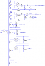
I've attached the power supply schematic again.
The ECC82 and 6H8C heaters are AC powered. Their heater wiring is less than optimum; tighter twists and relocation to the corners of the chassis would be good. But I don't want to rebuild these things. Lugging them around is going to give me a hernia!
My brief was to fix the 2 that hummed. The earthing in all 4 was so poor with the mains earth actually attached to the insulated negative speaker terminal in a couple of them that I couldn't return them in that state. But they did give some years of good service before 2 of them developed hums.
Meanwhile, I've relocated my PC-based test set-up to a table large enough to run the amps side-by-side and run the first 2 stages of a good amp into the output stage of the bad one and vice versa.
Attachments
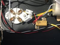
After an exhaustive process of elimination, I have tracked down the cause of the problem to one of the 25W 300B cathode resistors.

As you can see, the original builder didn't mount them properly. There's air underneath it. Despite dissipating only 5W, they get really hot. Not sure how a wire-wound resistor can degrade but it obviously has.
I really need to transfer all 8 of them to the chassis but that will be a lot of work.
As you can see, the original builder didn't mount them properly. There's air underneath it. Despite dissipating only 5W, they get really hot. Not sure how a wire-wound resistor can degrade but it obviously has.
I really need to transfer all 8 of them to the chassis but that will be a lot of work.
And how does this resistos measure? Curious, as the first question in the thread was indeed about the resistors, and you mentioned the currents through the valves were mathched.
So, transfer the (new) resistors to be in contact with the chassis, two bolts and thermal grease?
best regards,
Erik
So, transfer the (new) resistors to be in contact with the chassis, two bolts and thermal grease?
best regards,
Erik
The currents were indeed equal. It didn't occur to me to measure the problem resistor so I just did. Strangely, it's open circuit! Maybe the voltage applied by my meters isn't enough to get a reading.
I've already started moving the resistors in the first amp. The top plate is 1cm thick so I'll have to drill and tap it. I should really scrape the power coat off too.
Moving the resistors will keep me busy until the new resistor arrives.
I've already started moving the resistors in the first amp. The top plate is 1cm thick so I'll have to drill and tap it. I should really scrape the power coat off too.
Moving the resistors will keep me busy until the new resistor arrives.
If that resistor was poorly heat-sunk, it's value may have been modulated by temp changes from the signal current.
That alone would be enough to generate harmonic distortion.
Jan
That alone would be enough to generate harmonic distortion.
Jan
I pulled out the resistors and pots in one of the amps. 4 drilled and tapped holes later, the resistors are now screwed to the chassis with thermal paste.
Now that I can identify the pots, they're Bourns 3540S-91-101L. They're rated at 2W @ 75°C. My calculations suggest that with 70mA through the resistors, the pot centered and 5V across the filament (and the pot), power dissipation in the pot would be close to 2W.
Now that I can identify the pots, they're Bourns 3540S-91-101L. They're rated at 2W @ 75°C. My calculations suggest that with 70mA through the resistors, the pot centered and 5V across the filament (and the pot), power dissipation in the pot would be close to 2W.
So it is a 100R pot? It has the 5V across it, which makes for 50mA of current, and 0.25W of heat (P=V*I). Also 70mA through it. Still, how does this 70mA split over the resistor element? Say 35mA per side, and the pot is in the middle, so 50R on each leg, That makes for .035*.035*50 = 0.06W 2 = 0.12W. Hmm, is that right? Or calculate the worst case, where 70mA flows through the whole 100R, that would make .07.07*100 = 0.49W. Together with the 0.25W of the heating voltage, a total of 0.74W.
Wonder if the resistor only distorts when hot or it’s permanently compromised? The value can’t have changed because both tubes draw the same amount of current.
As I mentioned, if the resistor is inadequately cooled, its value changes with temperature in the rhythm of the signal.
The value changes with temperature and that changes with the signal. It only needs to be a fraction of a % but that's enough.
That means that the resistor value changes while operating and this causes distortion.
Let us say the resistor is nominally 1k. In the signal peaks, it heats up a few degrees so has a higher value, say 1001 ohms.
When the signal goes through zero it cools off to say 999 ohms. So the stage gain changes over a signal cycle -> distortion.
It's a well known mechanism due to resistor temperature coefficient.
Jan
Are you really sure? The resistors are bypassed with 68uF capacitor, hence the RC time constant dictates the rate of change. On top of that, you're talking talking about a 0.1% resistance modulation here. Again, with the capacitor restricting a high frequency of change. Should this result into an increase of 2% 2nd harmonc HD? How?
It makes more sense if the resistor was open-circuited, which means only one tube doing the job. Double Rp, double sloped loadline. Easily more second harmonic.
It makes more sense if the resistor was open-circuited, which means only one tube doing the job. Double Rp, double sloped loadline. Easily more second harmonic.

Those potentiometers were apparently used for AC filaments as hum balance pots.
But since the filaments apparently are now DC powered, the potentiometers should be replaced with 2 fixed resistors.
100 Ohm potentiometer replaced by two 50 Ohm resistors.
Or, if the filament DC is not filtered well enough, you will need more DC filtering, instead of a hum balance pot.
A really low voltage drop Schottky bridge might let you use a CRC filter for the filaments.
A 6.3V filament winding, Schottky bridge, 22,000uF, 2 Ohm resistor, 22,000uF has only 1mV ripple on a 300B filament.
No hum balance pot needed.
Some potentiometer wipers do not make a perfect contact, etc.
That could create noise and distortion.
Just my opinions
Thanks for this. The 300B filament DC currently has 10,000uF. Plenty of room for more.But since the filaments apparently are now DC powered, the potentiometers should be replaced with 2 fixed resistors.
100 Ohm potentiometer replaced by two 50 Ohm resistors. Or, if the filament DC is not filtered well enough, you will need more DC filtering, instead of a hum balance pot. A really low voltage drop Schottky bridge might let you use a CRC filter for the filaments.
Replacing the pots with 50Ω resistors would certainly simplify the process of attaching the cathode resistors to the chassis.
Good point, the bypass will limit it, at least at higher frequencies (where it will be limited anyway by the resistor thermal mass time constant).Are you really sure? The resistors are bypassed with 68uF capacitor, hence the RC time constant dictates the rate of change. On top of that, you're talking talking about a 0.1% resistance modulation here. Again, with the capacitor restricting a high frequency of change. Should this result into an increase of 2% 2nd harmonc HD? How?
It makes more sense if the resistor was open-circuited, which means only one tube doing the job. Double Rp, double sloped loadline. Easily more second harmonic.
69uF and 50R have an F3 freq of about 60Hz.
Do we know in which frequency range that extra distortion happens?
Jan
68uF is circa 2ohms at 1kHz, so even if the 1K resistance was modulated in value by 100% (wild!) it would only change the 2ohm impedance by about 0.2% leading to about +0.2% THD.
The resistance modulation due to self heating on such a large resistor occurs so slowly that it will only produce measurable distortion at sub sonic frequencies anyway. At 1kHz almost all the AC signal passes through the capacitor, the resistor sees almost constant/DC power dissipation so even if hypothetically it had no thermal mass and changed in temperature instantly in response to varying current, it would still remain at an almost constant temperature.
I find it more likely that one of the 1K resistors is open circuit or goes open circuit when it heats up, or one or both of the 68uF capacitors are faulty, or the OPT is faulty (incorrectly gapped). Reflow solder joints around hot parts as a cold solder joint can open up when heated. Resistors can usually tolerate about 150*C without issue - if they are allowed to get hotter than that then assume they are now faulty and replace with larger or better heatsunk parts.
Last edited:
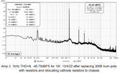
Any reason why moving the cathode resistors to the chassis and replacing the 10-turn pots with discrete resistors should increase the noise by 8dB or so?
Mind-you, I had this happen before so it could be external noise or something to do with my test set-up. I'll repeat the measurements later.
Mind-you, I had this happen before so it could be external noise or something to do with my test set-up. I'll repeat the measurements later.
Attachments
Looks like you may need trimpots after all. A testable theory is that the 100Hz spike is coming from ripple on the filaments' supply. Best course would be better filtering, but a lesser option is to add a 1K Ohm trimpot in parallel to the brick resistors. Ripple doesn't trim out perfectly, so it's always better to just filter it out, but worth a try, and both together are not against the law.
All good fortune,
Chris
All good fortune,
Chris
- Home
- Amplifiers
- Tubes / Valves
- Unexplained level of distortion in parallel 300B SE output stage