I’m repairing 4 parallel 300B SE amps. 2 hummed and all had very poor implementations of bus earthing.
Here’s the schematic

3 of the 4 amps measure well into 8Ω with 1kHz 1W THD around 0.5% at 1W.
The remaining one has distortion that is 5x worse at 2.5%.

The distortion profile at the SRPP output and the grids of the 300Bs is exactly the same as that in the other 4 amps which suggests the problem is something to do with the output stage.
Swapping 300Bs, SRPP tube, driver tube and rectifier tubes all have no impact on the distortion measurement.
Just to be sure that the OPT was setup for 8Ω I measured the voltage ratio: 14 for a primary impedance of 1580Ω with an 8Ω load. OK for parallel 300Bs.
Are there any potential sources of output stage distortion I’m missing here please?
Here’s the schematic
3 of the 4 amps measure well into 8Ω with 1kHz 1W THD around 0.5% at 1W.
The remaining one has distortion that is 5x worse at 2.5%.
The distortion profile at the SRPP output and the grids of the 300Bs is exactly the same as that in the other 4 amps which suggests the problem is something to do with the output stage.
Swapping 300Bs, SRPP tube, driver tube and rectifier tubes all have no impact on the distortion measurement.
Just to be sure that the OPT was setup for 8Ω I measured the voltage ratio: 14 for a primary impedance of 1580Ω with an 8Ω load. OK for parallel 300Bs.
Are there any potential sources of output stage distortion I’m missing here please?
I have no idea, but very curious. I assume replacing the OPT with a "good" one is rather hard? The voltage ratio is indeed ok,
Standing currents are ok, good, now, are the cathode bypass capacitors also ok?
Standing currents are ok, good, now, are the cathode bypass capacitors also ok?
Replacing the OPT would be a pain but not that hard. I could swap it for one on one of the other amps. 4 wires on each to desolder and re-solder, 4 nuts on each to undo and do-up.I have no idea, but very curious. I assume replacing the OPT with a "good" one is rather hard? The voltage ratio is indeed ok,
Standing currents are ok, good, now, are the cathode bypass capacitors also ok?
I wondered about the bypass caps. Currently they're big fancy 68uF 400V M-Caps. I'll see if I have anything I can try in there temporarily. Easier than switching the OPTs around.
Attachments

Try to desolder "bad" OPT wires, and temporarily solder (breadboarding) good OPT with enough long wires from "good" amplifier" (pulled out power tubes).
I tried different 300B cathode bypass capacitors but the distortion was the same. I'll try a different OPT next.
I should try different cathode resistors too. The amp builder didn't attach them to the chassis so they get very hot.
I should try different cathode resistors too. The amp builder didn't attach them to the chassis so they get very hot.
How do I look at the "distortion residual waveform". I would have thought REW could generate it but I'm not seeing how.Did you look at the distortion residual waveform? That's a useful diagnostic.
That is indeed odd. Assuming you already have swapped tubes, what remains is the output transformer or, the wiring on the output and to the measurement connections.The distortion profile at the SRPP output and the grids of the 300Bs is exactly the same as that in the other 4 amps which suggests the problem is something to do with the output stage.
Is the wiring around the output stage and OPT different between the one and the other three? Difference in grounding routing?
Jan
Are you sure, that hum-bucking potentiometers (RV1, RV2) are in same "position" (for example in middle)?
If the tubes are not "paired" (one is weaker than other), the distortion would growing.
If you change driving (wire from "good" amplifier R9 to "bad" C8//C9) the FFT remains the same?
If the tubes are not "paired" (one is weaker than other), the distortion would growing.
If you change driving (wire from "good" amplifier R9 to "bad" C8//C9) the FFT remains the same?
Yes, the 2 pots (10-turn ones) are both in the same centre position. Both 300Bs are labelled "Gm 52 Ip 5.2" which doesn't make a lot of sense. I put them on my curve tracer and the curves look good and matched.
I'll try running a good amp into C8||C9 tomorrow.
When I have the amps side-by-side I'll compare the wiring. Pretty sure I made them exactly the same.
I'll try running a good amp into C8||C9 tomorrow.
When I have the amps side-by-side I'll compare the wiring. Pretty sure I made them exactly the same.
I thought I'd found the problem this morning when I noticed that the 300B grid leak resistors were 470k instead of the 100k in the other 3 amps. I replaced them. Gain was reduced by a couple of dB and the distortion was still the same.
On to the side-by-side testing.
On to the side-by-side testing.
I find it difficult to believe one transformer is causing more distortion than the other. That would leave the resistors R12 and R14 or possibly the 10 turn pots. Wonder if the wattage rating of the pots is exceeded?
Thanks. Easier to try a temporary replacement of R12, R14 and the 10-turn pots than run 2 amps side-by-side with the output of the 6H8Cs into the other output stage so I'll try that first.
The 100 Hz & 100 Hz sidebands on the 1000 Hz test tone & its harmonics tells me there is a
problem in the power supply. Check the attachment of the PT CT to the first smoothing electrolytic,
the fault looks like the PS hum is bring injected into the negative buss.
problem in the power supply. Check the attachment of the PT CT to the first smoothing electrolytic,
the fault looks like the PS hum is bring injected into the negative buss.
I said it before. I will say it again . . .
Using AC power on DHT filaments will produce sidebands onto a test tone (at 2X the power mains frequency).
Example: Use a 1kHz test tone, and AC power for the 300B filament(s).
Power Mains that are 50Hz; the results are 900Hz lower sideband, 1kHz test tone, and 1100Hz upper sideband.
Power Mains that are 60Hz; the results are 880Hz lower sideband, 1kHz test tone, 1120Hz and upper sideband.
The level of the upper and lower sidebands versus the level of the test tone may vary; but those sidebands will be there.
The schematic of Post # 1 is not clear. It does not show for certain if the 300B filaments are AC powered . . .
But the "hum balance pot" in the 300B filament circuit almost certainly says they are AC powered.
Even if the full wave B+ is perfectly filtered, the AC DHT filaments will create the sidebands.
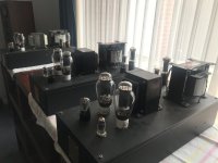
If I seen properly in #5 first picture, the 300B filament wires (yellow) goes to electrolyte capacitor, so it's DC heating.AC DHT filaments
Last edited:
- Home
- Amplifiers
- Tubes / Valves
- Unexplained level of distortion in parallel 300B SE output stage