Lingwendil,
what would be the reason for running the Concertina hotter than John Broskie had set it ?
Would the main benefit be the evenly distributed DC current through both halves of the 6N1P ? And would the benefit of that again be the more even wear on the two halves of the tube ? Or does it have something to do with the drive capability of the Concertina ?
If it's just for more even tube wear, my approach would be to set up the tubes for the respective channels in mirror-like fashion - in one channel, the Concertina would be on the left half of the tube; in the other channel, it would be on the right half. That way, I could swap the tubes between sides from time to time and even out the wear.
When I look at the data sheet of both the 6N1P and 6N1P-EV, for example the inter-electrode capacitances, the two halves look pretty symmetric to me - anything that would speak against this approach ?
I am slowly gathering parts for building this amp ... just got 100 pieces of 30k 2W 1% metal film resistors, so it would be no problem to try out 30k as well as 15k (by paralleling two 30k) on the Concertina ...
Also, I plan to buffer the B+ for each 6N1P with a 35 uF MKP cap per channel, so I am not terribly afraid of "non-constant" AC current draw ... 🙂
Best regards,
Claas
I would mainly do it to keep each half at similar DC conditions for wear, along with slightly (theoretically) better drive capability... No real delbreaker to run as shown though. Your idea for mirrored channels and rotating is a good one, and what I do on most point-to-point builds anyway, not likely to make a huge difference, but gives a good warm-and-fuzzy feeling 🙂
I liked the Tubecad EL84 so much. That I built a 6P1P version for my son. Obviously with lower voltages. red led this time where I had the schottkey last...under the first 6n1p.
Attachments

Last edited:
If one were to rework it for 12A_7 family of tubes I suppose the AT7 would be the closest in gm and mu but it is not so linear. If doing a stereo amp one could use a more linear tube for the VAS and the AT7 for the PI as it seems nearly ideal for that possition. Perhaps the AY7 or AX7 for the first possition as both are pretty linear. The AY7 has an advantage in biasing for. Grid input headroom and of requiring smaller plate load.
With a cathode resistor that isn't bypassed I think it's around ~20 or so, I have to check my notes.
Lovely 🙂
I really need to grab a few 6P1P at some point while they're still cheap.
I found these.
6P1P-EV Lot of 10Pcs Russian Audio Output Tubes OTK Stamp new industrial box | eBay
The price was $1 per tube when I bought a bunch of them... Now over $3!
I think I'll keep the 30 or so I have left and sell them when they go for $10 a piece 🙂
These are only $1.50 USD each if you get 50. 6P1P-EV / 6AQ5 / EL90 tube (new in paper) - Vacuum tubes - Tubes-Store.com
Many times one reads that the 6N1P is equivalent to the E88CC except for the filament current. Would the E88CC work in this setup without needing to change anything? I now use the 6N1P and I find my power transformer getting pretty hot (max 4.5A@6.3Vac) so reducing the filament current would probably help. I use led bias in the first stage.
Thanks!
Thanks!
I rebuilt this Eico HF-81 for a guy. He only wanted one input for his CD player. The tone controls were already bypassed. So out they went with the phono section. Added CCS fed shunt reg. for input and driver stage B+. There's something about shunt regulation that really picks up the sonics.
Attachments
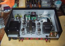
I think I may do shunt regulation on my next sweep tube amplifier- using the 12AV5GA and a DN2450 CCS fed VR tube for the screens. should be a nice way to go.
Tubecad EL84PP build documentation – optocoupler bias scheme
As already hinted at in my previous posts a few months back, I have been in the process of building this amp as well.
I wanted to build it in a modular fashion, so that later on I could try out different things. Maybe swap out the gain / concertina stage for a different front end, or try a different PP power stage, or a different biasing scheme …
Also, I wanted to try out a bias scheme a bit out of the ordinary. From my SS amp builds over at the Pass Labs forum, I am familiar with Nelson’s opto bias scheme, whereby an optocoupler is used in an automatic bias regulator for the output MOSFETs, for example as seen in the M2. I wanted to adapt this for the power tubes in this amp as well, and some SPICE simulation (my very first use of SPICE, actually) suggested that it might work. I adapted Nelson’s circuit to regulate grid-cathode voltage (fed from a negative bias supply) to keep cathode current constant, even under B+ variations (for example, due to line voltage variations), and always balanced, unaffected by tube aging.
Here is the little optocoupler automatic bias regulator module:

For the optocoupler to work, it needs a voltage of more than 1V, so for a typical bias of an EL84 a 33 Ohm current sense resistor would have to be placed into the circuit. I first tried it in the anode path, later in the cathode path. Simulation did not show any difference in regulation, testing worked well with both also. I chose to go with the cathode path because in that way I didn’t need to run the HV through the opto bias module. Maybe just a little bit safer.
I've also attached the circuit (in this iteration with current sensing in the anode connection) as a .pdf here.
The bias circuit has a time constant of maybe 15 seconds, so does only very slow bias adaptation. In static conditions, the bias scheme worked quite well both for a single tube and a PP pair.
Under load (tested with a sine input and an 8R dummy resistor at the output transformer secondary), I actually saw a problem. With each tube biased independently, the regulator dialed back the bias current under signal. If I remember correctly, it was something like that at about 2W output, the bias went from 36mA to maybe 26mA. That was not the only thing; it didn’t go down on both tubes the same amount, but slightly differently, causing unmatched bias under load. So when I later did distortion measurements on the completed amp, with a constant 1kHz sine signal, the output power went slowly down with the time constant of the bias circuit to some significantly lower value despite of constant input value, and the distortion figures were quite high at anything over 1W …
As I will also show later when I post about the build itself, I did a variation on the bias scheme that now actually works quite well. I use a common sense resistor for both tubes, in this case 16R. One side of the 16R goes to ground, the other to the wiper of a 20R trimmer that is used to balance the cathode currents of the EL84 pair. The other ends of the trimmer connect to the cathodes via a 1R resistor for current measurement.
In this way, I’ve lost the automatic balancing that independent bias circuits would have provided, but the DC bias (cathode current) is nicely stable, doesn’t vary with line voltage / B+ variations, and stays almost constant under load up to clipping. In a bias re-check after a few days / weeks, the cathode current is still at the value I set it. So, I would call this a partial success for “opto bias” so far.
As already hinted at in my previous posts a few months back, I have been in the process of building this amp as well.
I wanted to build it in a modular fashion, so that later on I could try out different things. Maybe swap out the gain / concertina stage for a different front end, or try a different PP power stage, or a different biasing scheme …
Also, I wanted to try out a bias scheme a bit out of the ordinary. From my SS amp builds over at the Pass Labs forum, I am familiar with Nelson’s opto bias scheme, whereby an optocoupler is used in an automatic bias regulator for the output MOSFETs, for example as seen in the M2. I wanted to adapt this for the power tubes in this amp as well, and some SPICE simulation (my very first use of SPICE, actually) suggested that it might work. I adapted Nelson’s circuit to regulate grid-cathode voltage (fed from a negative bias supply) to keep cathode current constant, even under B+ variations (for example, due to line voltage variations), and always balanced, unaffected by tube aging.
Here is the little optocoupler automatic bias regulator module:
For the optocoupler to work, it needs a voltage of more than 1V, so for a typical bias of an EL84 a 33 Ohm current sense resistor would have to be placed into the circuit. I first tried it in the anode path, later in the cathode path. Simulation did not show any difference in regulation, testing worked well with both also. I chose to go with the cathode path because in that way I didn’t need to run the HV through the opto bias module. Maybe just a little bit safer.
I've also attached the circuit (in this iteration with current sensing in the anode connection) as a .pdf here.
The bias circuit has a time constant of maybe 15 seconds, so does only very slow bias adaptation. In static conditions, the bias scheme worked quite well both for a single tube and a PP pair.
Under load (tested with a sine input and an 8R dummy resistor at the output transformer secondary), I actually saw a problem. With each tube biased independently, the regulator dialed back the bias current under signal. If I remember correctly, it was something like that at about 2W output, the bias went from 36mA to maybe 26mA. That was not the only thing; it didn’t go down on both tubes the same amount, but slightly differently, causing unmatched bias under load. So when I later did distortion measurements on the completed amp, with a constant 1kHz sine signal, the output power went slowly down with the time constant of the bias circuit to some significantly lower value despite of constant input value, and the distortion figures were quite high at anything over 1W …
As I will also show later when I post about the build itself, I did a variation on the bias scheme that now actually works quite well. I use a common sense resistor for both tubes, in this case 16R. One side of the 16R goes to ground, the other to the wiper of a 20R trimmer that is used to balance the cathode currents of the EL84 pair. The other ends of the trimmer connect to the cathodes via a 1R resistor for current measurement.
In this way, I’ve lost the automatic balancing that independent bias circuits would have provided, but the DC bias (cathode current) is nicely stable, doesn’t vary with line voltage / B+ variations, and stays almost constant under load up to clipping. In a bias re-check after a few days / weeks, the cathode current is still at the value I set it. So, I would call this a partial success for “opto bias” so far.
Attachments

Last edited:
Tubecad EL84PP build documentation - modular design
As stated earlier, I wanted to build the amp out of modules. I separated the front end from the EL84 PP module, and did build a small B+ buffer module as well, and bias modules.
All modules have been built on small glass fiber experimental boards, and have been wired using the component leads as much as possible. I used a lot of PCB screw connectors, both for connecting the modules together, and for mounting components that I might want to change later via the connectors, like cathode resistors, B+ dropping resistors, triode / pentode / UL connection, etc.
For output transfomers, I chose the following Toroidy EL84 PP transfomers:
TTG-EL84PP - Tube output transformer [8kOhm] 2xEL84 Push-pull or similar - Shop Toroidy.pl
I have had very good experiences with Toroidy power transformers, and for PP, a toroidal output transformer should also work well, if done correctly. There have been positive reports here about the Toroidy output transformers also. And, in their chrome cans, they just look cool … 😎
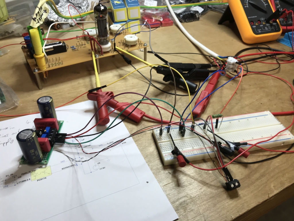
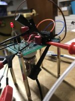
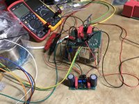
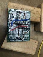
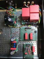
Here is the front-end module being tested:

And here the EL84PP module:

Here, I used the independent opto bias current regulators for each tube, and you can see the output transformer connected at the left of the picture.
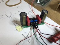
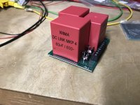
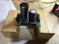
Because I use an external PSU connected with an umbilical, I built a B+ buffer board, using just MKP capacitors. For the main B+, it’s 120 uF, for the frontend, an additional 35 uF. The capacitors are WIMA DC-LINK (which is the same as their MKP4 series, as I understand it). The dropping resistor between main B+ and frontend B+ is connected “externally” via the screw terminals for easy voltage adaptation / dialing-in of the frontend.

I also built a small distribution module for the power inputs from the PSU (B+, heaters, negative bias) to connect to the other boards. On this board, there are some decoupling capacitors added for the heater supply and the negative bias voltage. The heaters are connected to ground here. Audio ground is connected to chassis ground via a CL-60.


As stated earlier, I wanted to build the amp out of modules. I separated the front end from the EL84 PP module, and did build a small B+ buffer module as well, and bias modules.
All modules have been built on small glass fiber experimental boards, and have been wired using the component leads as much as possible. I used a lot of PCB screw connectors, both for connecting the modules together, and for mounting components that I might want to change later via the connectors, like cathode resistors, B+ dropping resistors, triode / pentode / UL connection, etc.
For output transfomers, I chose the following Toroidy EL84 PP transfomers:
TTG-EL84PP - Tube output transformer [8kOhm] 2xEL84 Push-pull or similar - Shop Toroidy.pl
I have had very good experiences with Toroidy power transformers, and for PP, a toroidal output transformer should also work well, if done correctly. There have been positive reports here about the Toroidy output transformers also. And, in their chrome cans, they just look cool … 😎
Here is the front-end module being tested:
And here the EL84PP module:
Here, I used the independent opto bias current regulators for each tube, and you can see the output transformer connected at the left of the picture.
Because I use an external PSU connected with an umbilical, I built a B+ buffer board, using just MKP capacitors. For the main B+, it’s 120 uF, for the frontend, an additional 35 uF. The capacitors are WIMA DC-LINK (which is the same as their MKP4 series, as I understand it). The dropping resistor between main B+ and frontend B+ is connected “externally” via the screw terminals for easy voltage adaptation / dialing-in of the frontend.
I also built a small distribution module for the power inputs from the PSU (B+, heaters, negative bias) to connect to the other boards. On this board, there are some decoupling capacitors added for the heater supply and the negative bias voltage. The heaters are connected to ground here. Audio ground is connected to chassis ground via a CL-60.
Attachments

Tubecad EL84PP build documentation – amp construction
Construction was done into a 2U Modushop Galaxy case. All modules were mounted “to the ceiling”, using the perforated base that is available as an extra from Modushop mounted at the top of the amp, with holes for the tubes cut into it.
Case ground is carried separately on the umbilical from the PSU, and connected to the amp case near the connector. At the PSU, it is connected to PE / earth ground at the IEC connector.
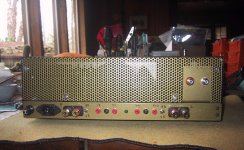
Back panel drilled, with the PSU umbilical connector in the middle. I used 7 of the 9 pins the connector offers.
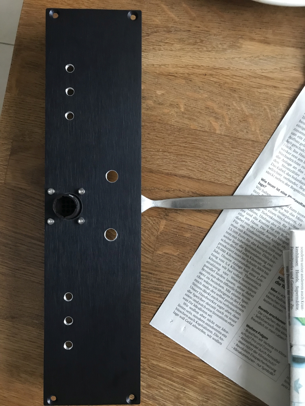
I drew up all holes in the back panel, the perforated steel base, and the top panels via a CAD program, printed the drawings out in original size, and used these as a drilling guide.
First fitting test:
One side wired up (frontend not yet wired)

Testing one completed side:

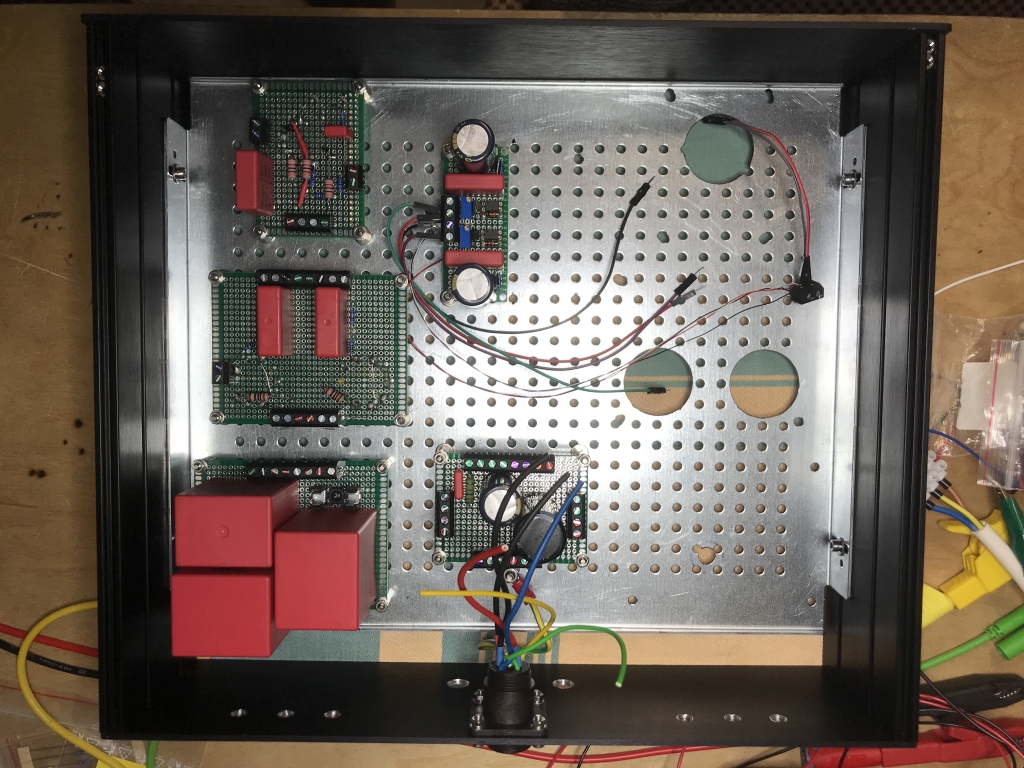
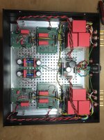
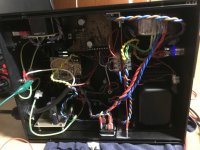
And the internal view of the completely stuffed amp:

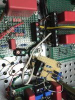
I mentioned in a previous post that my optocoupler-controlled bias scheme didn’t work out as intended when each tube was independently biased. So I changed to biasing a pair of tubes together via a common cathode current sensing resistor of 16R, and dialing in the balance between the two tubes using a 20R trimmer. Here is that little circuit added to the amp:

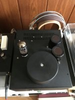
Now it’s time to talk about the PSU. I built this separately, originally for my Aikido build, from parts I had still laying around. For the Aikido, it is complete overkill; for this EL84PP amp, it actually works nicely 😀


Heater supply is via separate transformer, here a Toroidy 8.5V 80W unit. The heater voltage is regulated by an LT1084 with big heatsink – in the middle of the case, below the ventilation slots.
B+ is provided by tube rectification, followed by the big 10H choke in the lower left, followed by 2x 680 uF Aerovox capacitors. For the Aikido, I configured the HV supply as LCC, fronted by a 5C3S rectifier tube, and followed by a regulation circuit that provided approx. 240V.
For the EL84 amp, I use a GZ34 (less voltage drop / more current capability), and currently a 5 uF MKP4 as first capacitor for cLCC. Might need a bigger first cap here, as I am only getting 300-320V B+, depending on bias current and line voltage. The regulator is taken out of the circuit for the EL84 amp.
Then there is also the negative bias voltage regulated by another LT1084. In the Aikido, this powered the control circuitry and relays.
Here is the almost completed amp running in my system, still without the top plates:
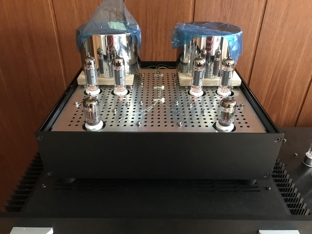
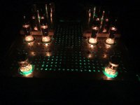
Amp at night (without top plate): 😉

The green glow that’s coming through the holes in the base plate is from the frontend cathode biasing LEDs. This is not intentional, and in the finished amp it’s totally unobtrusive 😛
Construction was done into a 2U Modushop Galaxy case. All modules were mounted “to the ceiling”, using the perforated base that is available as an extra from Modushop mounted at the top of the amp, with holes for the tubes cut into it.
Case ground is carried separately on the umbilical from the PSU, and connected to the amp case near the connector. At the PSU, it is connected to PE / earth ground at the IEC connector.
Back panel drilled, with the PSU umbilical connector in the middle. I used 7 of the 9 pins the connector offers.
I drew up all holes in the back panel, the perforated steel base, and the top panels via a CAD program, printed the drawings out in original size, and used these as a drilling guide.
First fitting test:
One side wired up (frontend not yet wired)
Testing one completed side:
And the internal view of the completely stuffed amp:
I mentioned in a previous post that my optocoupler-controlled bias scheme didn’t work out as intended when each tube was independently biased. So I changed to biasing a pair of tubes together via a common cathode current sensing resistor of 16R, and dialing in the balance between the two tubes using a 20R trimmer. Here is that little circuit added to the amp:
Now it’s time to talk about the PSU. I built this separately, originally for my Aikido build, from parts I had still laying around. For the Aikido, it is complete overkill; for this EL84PP amp, it actually works nicely 😀
Heater supply is via separate transformer, here a Toroidy 8.5V 80W unit. The heater voltage is regulated by an LT1084 with big heatsink – in the middle of the case, below the ventilation slots.
B+ is provided by tube rectification, followed by the big 10H choke in the lower left, followed by 2x 680 uF Aerovox capacitors. For the Aikido, I configured the HV supply as LCC, fronted by a 5C3S rectifier tube, and followed by a regulation circuit that provided approx. 240V.
For the EL84 amp, I use a GZ34 (less voltage drop / more current capability), and currently a 5 uF MKP4 as first capacitor for cLCC. Might need a bigger first cap here, as I am only getting 300-320V B+, depending on bias current and line voltage. The regulator is taken out of the circuit for the EL84 amp.
Then there is also the negative bias voltage regulated by another LT1084. In the Aikido, this powered the control circuitry and relays.
Here is the almost completed amp running in my system, still without the top plates:
Amp at night (without top plate): 😉
The green glow that’s coming through the holes in the base plate is from the frontend cathode biasing LEDs. This is not intentional, and in the finished amp it’s totally unobtrusive 😛
Attachments
-
 backpanel drilled.jpg931.7 KB · Views: 1,618
 -
 testing one complete side.jpg198.3 KB · Views: 1,607
 -
 one side partly wired up.jpg327.7 KB · Views: 1,601
 -
 fitting test.jpg617.3 KB · Views: 1,637
 -
 internal view of amp.jpg307.3 KB · Views: 1,826
 -
 common cathode resistor.jpg211.8 KB · Views: 1,583
 -
 PSU from top.jpg761.9 KB · Views: 1,564
 -
 PSU internals.jpg525.1 KB · Views: 1,553
 -
 amp at night without top plate.jpg535.3 KB · Views: 1,542
 -
 amp running - without top plate yet.jpg507.6 KB · Views: 1,536
Tubecad EL84PP build documentation – first conclusion
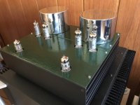
Here is a picture of the finished amp with the top plates, painted in green hammertone lacquer:

So, how does it sound ? I like it very much. Very clear, strong, clean bass, very transparent, lots of detail, 3D, engaging.
The amp by itself is very very quiet on my 100 dB/W widebanders. Almost undetectable amounts of noise and hum with my ear in the loudspeaker cone. 😉
As a preamp, I’m using Wayne’s BAF 2018 linestage at the moment. (My Aikido is missing a PSU ... 😛) When I switch that on, I hear some noise (tube rush ?) out of the speakers that is at some time more and at some time less. When the system is running for a few hours, it usually is rather quiet again. The whole system overall has a bit too much gain, and the volume control sits in front of the preamp, which has a bandwidth of more than 1 MHz …
I plan to experiment with two things: one, so far there is only a connection between audio ground and case ground via a CL-60 (10 Ohms). I want to try a 100 nF capacitor between audio ground and case directly at the gain stage input.
Second, maybe I should limit the bandwidth of the EL84 amp at the input, but have no good idea how to do that at the moment.
The amp has a bandwidth at 1W up to about 160 kHz for -3dB. Great iron 😉 At the lower end, it gets noticeably distorted on the scope below 10 Hz, and I guess that is to be expected 😛.
In the frontend, I am using very nice NOS Voskhod 6N1P-EV. Nicer than other 6N1Ps I tried. Have tried other tubes, but didn’t optimize the circuit for them to meet John Broskie’s operating points (5687, E182CC, 6N6P, E80CC). So I guess these others didn’t really have a chance … anyway, I’m really happy with the Voskhods.
For the power stage, I first tried a matched quad of JJ EL84s at 34mA. Nice mid, good clean and strong bass, a bit subdued highs. Right now, I’m running a quad (not matched) of 1979 Reflektor 6P14P-EV at 37mA. A bit stronger bass and much more prominent highs, but sound in balance throughout the spectrum. A bit more punch, but still very clean and engaging.
At the moment, this is my favourite amp, even over my SissySIT that I recently built (ZenMod probably would not like to hear that 😛) My 11 year-old son says that this is the best amp I built so far, but then, he is using the system with the Xbox … 😛😀
Here is a picture of the finished amp with the top plates, painted in green hammertone lacquer:
So, how does it sound ? I like it very much. Very clear, strong, clean bass, very transparent, lots of detail, 3D, engaging.
The amp by itself is very very quiet on my 100 dB/W widebanders. Almost undetectable amounts of noise and hum with my ear in the loudspeaker cone. 😉
As a preamp, I’m using Wayne’s BAF 2018 linestage at the moment. (My Aikido is missing a PSU ... 😛) When I switch that on, I hear some noise (tube rush ?) out of the speakers that is at some time more and at some time less. When the system is running for a few hours, it usually is rather quiet again. The whole system overall has a bit too much gain, and the volume control sits in front of the preamp, which has a bandwidth of more than 1 MHz …
I plan to experiment with two things: one, so far there is only a connection between audio ground and case ground via a CL-60 (10 Ohms). I want to try a 100 nF capacitor between audio ground and case directly at the gain stage input.
Second, maybe I should limit the bandwidth of the EL84 amp at the input, but have no good idea how to do that at the moment.
The amp has a bandwidth at 1W up to about 160 kHz for -3dB. Great iron 😉 At the lower end, it gets noticeably distorted on the scope below 10 Hz, and I guess that is to be expected 😛.
In the frontend, I am using very nice NOS Voskhod 6N1P-EV. Nicer than other 6N1Ps I tried. Have tried other tubes, but didn’t optimize the circuit for them to meet John Broskie’s operating points (5687, E182CC, 6N6P, E80CC). So I guess these others didn’t really have a chance … anyway, I’m really happy with the Voskhods.
For the power stage, I first tried a matched quad of JJ EL84s at 34mA. Nice mid, good clean and strong bass, a bit subdued highs. Right now, I’m running a quad (not matched) of 1979 Reflektor 6P14P-EV at 37mA. A bit stronger bass and much more prominent highs, but sound in balance throughout the spectrum. A bit more punch, but still very clean and engaging.
At the moment, this is my favourite amp, even over my SissySIT that I recently built (ZenMod probably would not like to hear that 😛) My 11 year-old son says that this is the best amp I built so far, but then, he is using the system with the Xbox … 😛😀
Attachments
Cost of amp and PSU
Hmm ... that is really not easy to say, because for most parts of the PSU, I used stuff that I had laying around from upgrading my diy 2A3SE amp, or that I bought as "byload" inexpensively from eBay (like choke and Aerovox caps) when the seller had some other interesting items besides my primary auction win.
What's also making it harder to calculate is the fact that when I order parts from Mouser, Reichelt, Arrow or somewhere else, I almost always order more than I need for that particular build - to have some spares, have more parts to match from, or just to build my inventory of parts for future builds or to whip up quickly some small circuit.
Let's try an estimate:
Toroidy TTG-EL84PP output transformers - 250 EUR incl. shipping
other transformers, choke and caps - maybe 200 EUR
two cases with the amp top plates cut to order - 100 EUR incl. shipping
all other parts and connectors - probably close to 200 EUR
So all in all, I guess it's around 750 EUR.
Connectors alone are about 60 EUR, especially the speaker connectors and the professional 9-Pin connector for the umbilical ain't cheap.
But then, I really built this amp as a platform to try more things later, which makes it much more complicated as necessary, and also more expensive - just for the amount of screw terminals alone ... 😛
The PSU I already have adapted from usage with my Aikido, the adaptation has worked out quite well and easy. But it really is an overkill PSU. 😀
And the Toroidy output transformers are just great ... 😉😎
In order to just build the amp, I probably wouldn't go this modular route (again), way too much work; instead, probably try to find a PCB for this amp, or something like a Baby Huey, or a Red Light District amp, ...
That way it is probably much easier to build and less expensive.
Hope this helps,
regards, Claas
Dear all,
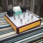
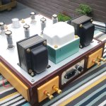
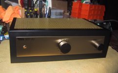
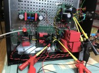
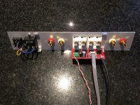
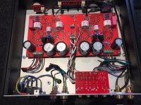
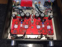
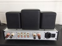
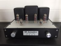
This is my version of the EL84 amplifier. I tried to make it a small integrated amp and I'm pretty happy about it. As can be seen on the picture of the PCB, the 6N1P is LED biased while the EL84s use a LM317. I didn't expect The LM317 to get that hot by the 80 mA going through it so I had to mount a small heatsink on each afterwards. If I would have thought about it before i would have left more space for it on the PCB and the heatsink could have been fixed to the PCB (now its only connected to the LM317).
Output transformers are from Hammond (1650E) power transformer from Toroidy. Top and back and bottom plate are from schaeffer-ag.de (I do not have fun in drilling and cutting etc and they do it so much better for an ok price).
The rest is standard I suppose.
Buying all the parts new, and having PCBs and front panels made, doesn't make the project cheap, but it's a fun project, and I'm happy with the outcome.
It's nicely playing in our garden house/conservatory connected to a pair of super mini monitors ( W15CY001-OWI ) which makes a nice combo.
Cheers,
Attachments
- Home
- Amplifiers
- Tubes / Valves
- Unexpectedly good EL84 amp