The PE wire should be a little longer than the Phase and Neutral wires. That is to guarantee that the PE wire is the last to come loose, if the mains cable is torn off.AndrewT said:Take the mains third wire (protective earth) direct to chassis and make this connection a permanent mechanical fixing. Probably better to keep this wire short
yes.samsagaz said:the only change is to connect the chassis directly to the Ground from Mains, instead to the Loop.
Take that green incoming wire back to the chassis and keep the chassis connected to the Network with the other green wire.
agreed, when using a cable entry.pacificblue said:The PE wire should be a little longer than the Phase and Neutral wires. That is to guarantee that the PE wire is the last to come loose, if the mains cable is torn off.
DAC grounding with two power supplies
Hi everybody,
I've been following this topic with great interest for quite a while.
I've seen a lot of great ideas but none of them fit the design of my DAC i'm currently building.
The biggest problem is that my DAC will have two power supplies and that makes it a bit more difficult for me to know if I make the right decision with my grounding scheme.
I made two grounding ideas today:
Idea 1:
Idea 2:
I would really appreciate it if you can give me some feedback on my grounding schemes I made so far.
Thank you very much in advance.
Hi everybody,
I've been following this topic with great interest for quite a while.
I've seen a lot of great ideas but none of them fit the design of my DAC i'm currently building.
The biggest problem is that my DAC will have two power supplies and that makes it a bit more difficult for me to know if I make the right decision with my grounding scheme.
I made two grounding ideas today:
Idea 1:
An externally hosted image should be here but it was not working when we last tested it.
Idea 2:
An externally hosted image should be here but it was not working when we last tested it.
I would really appreciate it if you can give me some feedback on my grounding schemes I made so far.
Thank you very much in advance.
I think I prefer pic4, with the D/A earth separate from the digital earth.
Where is the analogue earth?
I would be tempted to try disconnecting networks from chassis to each of the PCB earths.
Where is the analogue earth?
I would be tempted to try disconnecting networks from chassis to each of the PCB earths.
Just remember guys that if you do use your steel chassis as the main 'star-point' of your star earth system that steel is way less conductive than copper. I could dig out the exact spec's on conductivity if you want but I am sure it would be quicker to search around the 'net for these figures.
May I suggest a brass, maybe nickel-plated (due to the skin-effect), earth block where you can attatch all your earths back into and create a true star. Where you connect this earth block to depends on how you are configuring your power supplies, i.e. ClassII (double insulated) has a centre-tapped earth point.
Gareth
P.S. Nickel has more electrons in it's valency shell too than copper, so it is more conductive.
Skin-effect in a star-ground? 😕
The chassis should never be used as a conductor. The star-point should be, what its name specifies, a point as ideal as posisble. E. g. a bolt makes for a good star point. A massive block of copper or aluminium makes also for a good star-point. A chassis makes for a good ground-loop.
Double-insulated equipment has no earth connection.
Nickel - 14,3*10^6 S/m
Brass - 15,5*10^6 S/m
Aluminium - 36,59*10^6 S/m
Copper - 58*10^6 S/m
pacificblue said:Skin-effect in a star-ground? 😕
The chassis should never be used as a conductor. The star-point should be, what its name specifies, a point as ideal as posisble. E. g. a bolt makes for a good star point. A massive block of copper or aluminium makes also for a good star-point. A chassis makes for a good ground-loop.
Double-insulated equipment has no earth connection.
Nickel - 14,3*10^6 S/m
Brass - 15,5*10^6 S/m
Aluminium - 36,59*10^6 S/m
Copper - 58*10^6 S/m
I think you misunderstood the point I was trying to make about the skin-effect but nevermind. As you say the chassis should never be used as a star point, nut and bolt maybe but a dedicated 'block is a better option IMO. A star point is a centarl main earth terminal where others can return to. And yes, obviously, CLass II/double insulated has no supply (cable) earth it is taken from the centre-tap of the secondary winding of the equipment transformer.
Maybe uranium coated silver star-point blocks then??
How about silver plated copper solder tags??
Bolt them together with a silver plated copper bolt or screw with copper nut or any non ferrous nut.
Bolt them together with a silver plated copper bolt or screw with copper nut or any non ferrous nut.
Platinum, Uranium, Nickel, Brass?
I thought we were discussing electrical conductivity.
What are the benefits of these four materials cf. Silver, Copper, Aluminium?
I thought we were discussing electrical conductivity.
What are the benefits of these four materials cf. Silver, Copper, Aluminium?
AndrewT said:I think I prefer pic4, with the D/A earth separate from the digital earth.
Where is the analogue earth?
I would be tempted to try disconnecting networks from chassis to each of the PCB earths.
There's hardly an analogue ground. The D/A board contains 8 TDA 1543 chips which are earthed. From there the analogue audio only goes to a passive I/V stage with a resistor going to GND and a capacitor, then to the analogue outputs. No filter stage or what so ever is used for the I/V conversion. The GND of the TDA chips and I/V resistor is the same on the board.
I've spoken some more people about my grounding scheme and they actually say the same: Try not to make the GND connection from the PCB's to the chassis.
If that gives problems try earthing via decoupling to the chassis.
Hi guys,
I tried to post this in the power supply section and the solid state section but haven't got any help from anyone, so I am wondering if someone can help me here.I am currently building an 8 channel Leach amp, I would like to know the best and safest way to connect all 8 channels to the power supply. I am using a Toroidal transformer which has the following secondary outputs (45-0-45 & 45-0-45), there is a total of 8 wires on the secondary side. How would be the best way to connect the 8 channels so as to avoid getting any hum,but also keeping things safe.
Any info would be great.
Cheers
Bowdown
Leach runs fairly high output bias current.
How do you plan to dissipate the quiescent heat from 8channels?
How do you plan to dissipate the quiescent heat from 8channels?
hey Andrew,
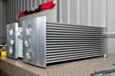
I have 2 huge heatsinks at 600mm long by 250mm wide and rated at around 0.2 Degrees C/W each, Reading the Leach amp plans, it says you need around 0.67 Degrees C/W for each channel, so ideally I should have 0.67 / 4 channels = 0.1675 Degrees C/W. I thought to make up the extra bit I could add a couple of fans for extra cooling once the sinks get to like 45 - 50 Degrees C. I could just build a 6 channel version but I thought I might as well try and add an extra 2 channels if I can so I can run another stereo zone. Bear in mind all the channels will not be running together all the time mainly only channels 1-6 will be used most of the time as its for a home theatre setup.
See the pic attached for what it will look like (still in progress).
cheers
Bowdown
P.S - I know that the heatsinks are not in the optimum orientation either,I couldn't really use them the other way around.
Attachments
Hi,
if you stand the amplifiers upright you will get nearer that 0.2C/W rating, but only if the Ts-Ta temperature difference matches the deltaT s-a that the manufacturer used to rate the heatsink.
You will also need to ensure that the whole backplate temperature is held at Ts. Not just the small areas contacting the transistors. This will further de-rate the heatsink.
You may find that the sink lying horizontal will dissipate @ ~0.4C/W when de-rated for your actual installation parameters.
A 45-0-45Vac transformer will feed ~135Vdc to the amplifiers.
8channels each with a 2pair output stage, biased to 45mA, will require to dissipate ~100W @ quiescent condition. That is going to be mighty hot.
If you cut the 600long heatsink into shorter lengths, you will find that the total heatsink dissipation will improve markedly.
Cut them in half ( 300 tall by 250 wide) will gain 40% in dissipation capacity.
Cut them into 4 (150 tall by 250 wide) will double the dissipation capacity.
These cut down sinks will better suit single channel or two channel amplifiers.
If you want to try his suggested increase in bias current from 45mA to 70mA (Iq from 100mA to 150mA) then the amps will run even hotter.
if you stand the amplifiers upright you will get nearer that 0.2C/W rating, but only if the Ts-Ta temperature difference matches the deltaT s-a that the manufacturer used to rate the heatsink.
You will also need to ensure that the whole backplate temperature is held at Ts. Not just the small areas contacting the transistors. This will further de-rate the heatsink.
You may find that the sink lying horizontal will dissipate @ ~0.4C/W when de-rated for your actual installation parameters.
A 45-0-45Vac transformer will feed ~135Vdc to the amplifiers.
8channels each with a 2pair output stage, biased to 45mA, will require to dissipate ~100W @ quiescent condition. That is going to be mighty hot.
If you cut the 600long heatsink into shorter lengths, you will find that the total heatsink dissipation will improve markedly.
Cut them in half ( 300 tall by 250 wide) will gain 40% in dissipation capacity.
Cut them into 4 (150 tall by 250 wide) will double the dissipation capacity.
These cut down sinks will better suit single channel or two channel amplifiers.
for 40-0-40Vac transformer.Reading the Leach amp plans, it says you need around 0.67 Degrees C/W for each channel,
If you want to try his suggested increase in bias current from 45mA to 70mA (Iq from 100mA to 150mA) then the amps will run even hotter.
Hey Andrew,
Thanx for the info..I totally overlooked and didnt take the extra voltage into consideration..hmmm will have to get back onto the drawing board..in any case i will still need to make a multichannel amp, so what would be the best way to ground the whole lot?
Thanx heaps for ur info
Cheers
Bowdown
Thanx for the info..I totally overlooked and didnt take the extra voltage into consideration..hmmm will have to get back onto the drawing board..in any case i will still need to make a multichannel amp, so what would be the best way to ground the whole lot?
Thanx heaps for ur info
Cheers
Bowdown
Hi Andrew,
I just had another look at the data sheet for the sink and it says its about 0.07 Degrees C/W fan cooled for a 300mm length with the fins vertical, so that should be 0.035 Degrees C/W for a mm Length at a temp rise of Degrees C. I knowI would get less than that but if I left the sinks the way they are and had fan cooling internally with the fans taking the heat out, do you think I should have close to 0.1 Degrees C/W? Attached is the sink data sheet. Let me know what you think.
Also looking at the data sheet from wakefields website for the sink recommended by Leach, it says that the thermal efficiency of the sink is 47 Degrees C for 50 watts, natural convection and 0.5 Degrees C/W with forced cooling with a 250LFM fan. The sink recommended by Leach is the 423K its on the bottom of the second page on the below link.
http://www.wakefield.com/PDF/extruded_heat_sink.pdf
cheers
Bowdown
Attachments
rhodes54 said:
I've spoken some more people about my grounding scheme and they actually say the same: Try not to make the GND connection from the PCB's to the chassis.
If that gives problems try earthing via decoupling to the chassis.
I agreed.There are two ground in case we need to deal with.One is earth ground,the other is work ground.
The earth ground is for safe.when I make a device,I consider the earth ground outside the device.
The work ground is a return path via ground electrodes.this return path is complicated,it involves power supply ground,signal ground,digital ground.I consider the work ground is not stand alone,because the return path is between the audio gear via connections cable.
Zang
Re: DAC grounding with two power supplies
here is my plan.
the blue line is work ground.in this case you need not star grounding.
the green line is earth ground to chassis.
for cut off the latent ground loops.do not connect the blue line to the chassis.do not use two blue lines connect to the out put RCA pairs,single ground line is the best.
P.S.
how it works still up to the pcb design.
rhodes54 said:
The biggest problem is that my DAC will have two power supplies and that makes it a bit more difficult for me to know if I make the right decision with my grounding scheme.
here is my plan.
the blue line is work ground.in this case you need not star grounding.
the green line is earth ground to chassis.
for cut off the latent ground loops.do not connect the blue line to the chassis.do not use two blue lines connect to the out put RCA pairs,single ground line is the best.
P.S.
how it works still up to the pcb design.
Attachments
- Home
- Amplifiers
- Power Supplies
- understanding star grounding