Hi Eivind,
In step 4. above, also measure the resistance between each buss and the chassis. There should be no connection there either. If there is a connection, find it and remove it.
Dave
In step 4. above, also measure the resistance between each buss and the chassis. There should be no connection there either. If there is a connection, find it and remove it.
Dave
Aikido/F4 grounding problems
David
Se my note in # 154. There is no ground connection directly from Aikido and to F4.
F4 has one common ground point where ground in, ground out to loudspeaker and power common ground ( 0 V) meets. This common ground point goes to buss A (right channel) .
Left channel = identical.
After I have tried a third DN (Andrews adwise)I will try to do yours to morrow.
Eivind Stillingen
Hi Eivind,
Sorry for the confusion, let me try again:
First, isolate the different grounds:
1. Remove all disconnecting networks.
2. On buss C, remove the Inground from F4, both right and left channels.
3. On buss C, remove ground from RCA in-socket, both right and left channel.
4. Remove wires from chassis to buss A, buss B and buss C.
Second, verify that the busses and the chassis are isolated.
5. Measure the resistance between the three busses in both channels and from each buss to the chassis to make sure that there is no connection - sneak back path. If there is a connection between the busses or chassis, find it and remove it.
Third, re-connect the grounds, but a little different than they were before.
6. Connect a wire from buss A to the common star at the chassis.
7. Connect a wire from buss B to the common star at the chassis.
8. Connect a wire from buss C to the common star at the chassis.
9. Connect a wire from the Inground from F4, both right and left channels to the common star at the chassis.
10. Connect the RCA input ground to the common star at the chassis (both channels). It is important that the RCA input ground be connected to the star rather than to buss C.
11. Connect the mains safety ground to the common star at the chassis.
Buss A now has:
· Loudspeaker ground from F4, right channel.
· Common power supply (0 V) from F4 power PCB board, right channel.
· Negative loudspeaker outlet, right channel.
. Connection to the common star at the chassis.
Buss B now has:
. Same as buss A except left channel.
Buss C now has:
· Aikido ground (the star point on the PCB).
· Power ground from BAS power supply for Aikido.
· Connection to the common star at the chassis.
Note that disconnecting networks are not used.
Dave
step 11 is dangerous.
Connect the mains cable protective earth (PE or third wire) permanently to the chassis very near where it enters the chassis.
Never remove it.
If it is shared with other connections there is a real danger that some day you will inadvertently loosen/disconnect it and switch on.
Connect the mains cable protective earth (PE or third wire) permanently to the chassis very near where it enters the chassis.
Never remove it.
If it is shared with other connections there is a real danger that some day you will inadvertently loosen/disconnect it and switch on.
Hi Andrew,
I agree with you,,, partially 🙂
I agree that the mains safety ground should be connected to the chassis near where it enters the chassis.
However, I do not have a problem with making this point the system star ground. The way that I do it is to connect a heavy buss wire from the ground pin on the IEC power connector to a screw adjacent to the connector. I use the buss wire as the system star ground. There is no way that this will come loose.
Dave
Attachments
I too have no problem with where one chooses to locate the main Audio Ground.
The safety issue is the permanence of the PE to chassis connection. It should never require to be dismantled when any other wiring is being modified.
I do not like your pic layout. The star ground is not, it is distributed along the "buss".
The safety issue is the permanence of the PE to chassis connection. It should never require to be dismantled when any other wiring is being modified.
I do not like your pic layout. The star ground is not, it is distributed along the "buss".
Aikido/F4 grounding problems
David
I have followed your plan from point one to ten. Point eleven, the mains safety ground I will do later.
Point nine: Connect inground on F4, both left and right, to the common star at the chassis. This can not be done:
There is no separate inground on F4: Se my note on that in post #154:
F4 has, as Aikido, one common ground point on the board. This common point serve as:
F4 ground in
0 V from power pcb
ground loudspeaker out
I can do this connection:From star ground---->to the second conductor on the shielded wire from Aikido----->to ground on F4.
I can not see how this could be correct, since I now will have two different connection from F4s ground, since I already have another ground connection to buss A and B (this will give me another loop???).
David, as you already have understood, I still have hum and buzz.
It is difficult to say how much it hums because the buzz is so dominant.
I am close to give up and put Aikido into a separate case.
Do you (or other) still have any advices??
Eivind Stillingen
Hi Eivind,
Now I am confused. From post #154:
What is the "Inground from F4, both right and left channel" to buss C? But it does not matter. What is important is that each buss A, B and C is isolated and then connected to a single point along with anything else that needs to be grounded.
Don't give up yet, grounding can be elusive but it can be solved. I am willing to stay with you until the problem is solved.
My next step would be to do step 11 now. I speculate that the power supply transformers are creating AC leakage currents that need to get back to earth ground and are going through the signal wiring to get there.
Dave
Now I am confused. From post #154:
Originally posted by Liliya
To buss A (right channel):
· Loudspeaker ground from F4, right channel.
· Common powersupply (0 V) from F4 power PCB board, right channel.
· Negative loudspeaker outlet, right channel.
To buss B (left channel)
· Same as buss A, but left channel.
To buss C:
· Aikido ground (the star point on the pcb).
· Inground from F4, both right and left channel (??? Se note).
· Powerground from BAS powersupply for Aikido.
· Ground from RCA in-socket, both right and left channel.
What is the "Inground from F4, both right and left channel" to buss C? But it does not matter. What is important is that each buss A, B and C is isolated and then connected to a single point along with anything else that needs to be grounded.
Don't give up yet, grounding can be elusive but it can be solved. I am willing to stay with you until the problem is solved.
My next step would be to do step 11 now. I speculate that the power supply transformers are creating AC leakage currents that need to get back to earth ground and are going through the signal wiring to get there.
Dave
So, is there any problem with this diagram by gni?
http://www.diyaudio.com/forums/showthread.php?postid=1509392#post1509392
Also, can anybody tell me if such a disconnecting network is legal in Canada, i.e. will my insurance company screw me if they find out I used one?
Third, is there any benefit to using a higher-power resistor?
Fourth, what should the capacitor be rated at? A 250VAC cap will suffice, correct?
More questions:
does the safety earth connection as shown in the picture need to be permanent or can it be made a part of the cable?
Should each amp be fused separately after the PS? If so, should it be on both +/- rails?
does the safety earth connection as shown in the picture need to be permanent or can it be made a part of the cable?
Should each amp be fused separately after the PS? If so, should it be on both +/- rails?
Only, if they can prove that the disconnection network produced a case for them, which is very unlikely. It is rather going to save them a case.454Casull said:i.e. will my insurance company screw me if they find out I used one?
Anyhow they would probably be more upset about the fact that it is DIY, rather than about the network as such. So you should be able to prove to them, that everything was done just as good as if made by professionals.
Only, if you use it at higher ambient temperature.454Casull said:Third, is there any benefit to using a higher-power resistor?
The voltage across the cap is limited by the rectifier and should remain below 2 V.454Casull said:Fourth, what should the capacitor be rated at? A 250VAC cap will suffice, correct?
It can be part of the cable on the condition that the earth connection is the first to make contact and the last to unmake contact, when you plug or unplug the cable. Choose a connector type that has a dedicated PE connection, and is therefore designed to guarantee that.454Casull said:does the safety earth connection as shown in the picture need to be permanent or can it be made a part of the cable?
You must provide an overload fuse for the transformer's secondary for safety reasons rated at the nominal output current slow-blow. You should provide fuses for the electronic components rated according to the datasheets specifications and fast-blow. Having separate fuses for each amplifier makes fault detection easier, but is not mandatory. It could however become mandatory to use them for wire protection, e. g. if the transformer secondary is fused with 20 A, but the wires to each amplifier channel are only capable of 10 A.454Casull said:Should each amp be fused separately after the PS? If so, should it be on both +/- rails?
the maximum voltage across the paralleled bridge rectifier is the Vf at the fault current that passes.454Casull said:So, is there any problem with this diagram by gni?
Third, is there any benefit to using a higher-power resistor?
Fourth, what should the capacitor be rated at? A 250VAC cap will suffice, correct?
This is likely to a very few volts. It will certainly be well above the standard Vf=700mV that everyone assumes for normal bridge currents.
Now look at what is needed in parallel if the maximum voltage is say 4Vac. Power resistor no, 600mW probably. 250Vac capacitor no, 50Vdc probably.
I cannot answer to Canada's regulations.
Aikido/F4 grounding problems
Being busy on work, I went to my Aikido/F4 project yesterday.
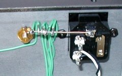
Buss A and B was disconnected again. All wires coming from F4: ground out, common earth from the powerboards and loudspeaker out was taken away. First of all I checked that there was no connection to the chassis, and like before, there was none.
Next: I mounted each wire back to buss A and B, and at the same time I had my multimeter connected to each busses. Result: A connection between buss A and B occured!!??. The connection I measured was around 2 Mohm. I must admit I did not, and I still do not understand this results.
Theoretical there should not be any connection between the two power units for the two F4.
David, you gave an idea in your last post: The powerunits. So far all attention have been paid on other parts of the amplifier.
I was curious to find out, so I dismounted Aikido temporarily (the chassis is very cramped)
To be honest I did not find out anything that could do me any wiser or give me an answer to the connection between buss A and B, but I found something else. On one of the F4 board both joints on C3 was broken. Nothing else was found. My hope was that repairing the problems around C3 should be the solution to all my problems.
Putting back all wires to the two busses, there was still a connection between the buss A and B. Searching for a way to break this connection, I found out that if I removed the signal
connection from Aikido to F4, I also removed the connection between buss A and B???????
Well, keeping an opportunity to listen to the amplifier, I had to do the connection from Aikido to F4 again. I even established a connection from F4 common ground (in) to the chassis ground. I thought, why not, even if I was afraid of creating just a new ground loop, I could also try do to this.
Results was promising: No hum but still a brrrrrrrrrrrrrrrrrrrrrrrrr that I could not accept listening on my headphones.
Next step: How would a listening trough my loudspeaker (my background loudspeaker when I look/listen to movis) behave??
First thought: I must have done something wrong, nothing came out from the speakers. I moved to them, putting my ears very close to them. The amplifier was “in” but no hum nor any disturbing brrrrrrrrrrrrrrrrrrrr.
I was so surprised. Why on earth do I have a quiet amplifier connecting a pair of 8 ohm loudspeakers, but problems when I listen to headphones (ca. 60 ohm)???? Of course I now that a headphone is much more sensitive to noise in the signal, but why this big difference. Can anyone explain this to me ?????f
Now I am satisfied. I can very live with the situation now. My long story about ground loops has come to and end.
I am very thankful David and Andrew in particular for their contribution.
My next step, where I also need some help, will be: The gain from my Aikido is a little bit to high, so I want to lower it. Changing the value of Rk is necessary, but must also other changes be done??
Eivind Stillingen
Being busy on work, I went to my Aikido/F4 project yesterday.
Buss A and B was disconnected again. All wires coming from F4: ground out, common earth from the powerboards and loudspeaker out was taken away. First of all I checked that there was no connection to the chassis, and like before, there was none.
Next: I mounted each wire back to buss A and B, and at the same time I had my multimeter connected to each busses. Result: A connection between buss A and B occured!!??. The connection I measured was around 2 Mohm. I must admit I did not, and I still do not understand this results.
Theoretical there should not be any connection between the two power units for the two F4.
David, you gave an idea in your last post: The powerunits. So far all attention have been paid on other parts of the amplifier.
I was curious to find out, so I dismounted Aikido temporarily (the chassis is very cramped)
To be honest I did not find out anything that could do me any wiser or give me an answer to the connection between buss A and B, but I found something else. On one of the F4 board both joints on C3 was broken. Nothing else was found. My hope was that repairing the problems around C3 should be the solution to all my problems.
Putting back all wires to the two busses, there was still a connection between the buss A and B. Searching for a way to break this connection, I found out that if I removed the signal
connection from Aikido to F4, I also removed the connection between buss A and B???????
Well, keeping an opportunity to listen to the amplifier, I had to do the connection from Aikido to F4 again. I even established a connection from F4 common ground (in) to the chassis ground. I thought, why not, even if I was afraid of creating just a new ground loop, I could also try do to this.
Results was promising: No hum but still a brrrrrrrrrrrrrrrrrrrrrrrrr that I could not accept listening on my headphones.
Next step: How would a listening trough my loudspeaker (my background loudspeaker when I look/listen to movis) behave??
First thought: I must have done something wrong, nothing came out from the speakers. I moved to them, putting my ears very close to them. The amplifier was “in” but no hum nor any disturbing brrrrrrrrrrrrrrrrrrrr.
I was so surprised. Why on earth do I have a quiet amplifier connecting a pair of 8 ohm loudspeakers, but problems when I listen to headphones (ca. 60 ohm)???? Of course I now that a headphone is much more sensitive to noise in the signal, but why this big difference. Can anyone explain this to me ?????f
Now I am satisfied. I can very live with the situation now. My long story about ground loops has come to and end.
I am very thankful David and Andrew in particular for their contribution.
My next step, where I also need some help, will be: The gain from my Aikido is a little bit to high, so I want to lower it. Changing the value of Rk is necessary, but must also other changes be done??
Eivind Stillingen
Thanks, pacificblue, Andrew.
What do you suggest as a removable connection? Peak current will likely be no more than 30A.
So, fuse the primary near the entry module, fuse the secondary, then optionally fuse each amp?
pacificblue said:
It can be part of the cable on the condition that the earth connection is the first to make contact and the last to unmake contact, when you plug or unplug the cable. Choose a connector type that has a dedicated PE connection, and is therefore designed to guarantee that.
::
You must provide an overload fuse for the transformer's secondary for safety reasons rated at the nominal output current slow-blow. You should provide fuses for the electronic components rated according to the datasheets specifications and fast-blow. Having separate fuses for each amplifier makes fault detection easier, but is not mandatory. It could however become mandatory to use them for wire protection, e. g. if the transformer secondary is fused with 20 A, but the wires to each amplifier channel are only capable of 10 A.
What do you suggest as a removable connection? Peak current will likely be no more than 30A.
So, fuse the primary near the entry module, fuse the secondary, then optionally fuse each amp?
A simple MKT cap should work fine then, right?AndrewT said:the maximum voltage across the paralleled bridge rectifier is the Vf at the fault current that passes.
This is likely to a very few volts. It will certainly be well above the standard Vf=700mV that everyone assumes for normal bridge currents.
Now look at what is needed in parallel if the maximum voltage is say 4Vac. Power resistor no, 600mW probably. 250Vac capacitor no, 50Vdc probably.
I cannot answer to Canada's regulations.
Connectors can be rated for the average current. They must not withstand the peak current. A 30 A rated connector would be extremely big, because it would have to accomodate 6 mm² wires.454Casull said:What do you suggest as a removable connection? Peak current will likely be no more than 30A.
An elegant, but expensive solution is the N6R series from Hirschmann (250 V, 10 A). They are industrial connectors that are used e. g. for servo motors, and are available from other manufacturers as well. If you don't have crimping tools, look for solderable versions.
Nice and small are sensor connectors M8 (30 V, 3 A) or M12 (250 V, 4 A). You can see them on the same site, and they are also available from other manufacturers.
ASR uses these (400-1000 V, 22-100 A ratings) in their Emitter. They are IP65 rated and normally used in the toughest industrial environments. Somewhat exaggerated for audio applications with highly debatable aesthetic value.
Yes.454Casull said:So, fuse the primary near the entry module, fuse the secondary, then optionally fuse each amp?
gareth said:As Andrew T has stated, never put resistance onto your safety earth.
Under fault condition there will be :-
a) high AC voltage on any exposed metalwork (OUCH!)
b)your protective devices will not operate properly in the specified
time (double OUCH!!)
I stil dont get it.
How is a shock possible from touching only one point?
Im not disputing that its possible I have been shocked myself in this way I simply dont understand how it works.
Further, it seems absurd that current travels through the floor and up my feet. There is no way current can travel in this way given that the floor is an insulator which is many millions of ohms.
correct.Professor smith said:I simply dont understand how it works.
wrong.Professor smith said:
Further, it seems absurd that current travels through the floor and up my feet. There is no way current can travel in this way given that the floor is an insulator which is many millions of ohms.
AndrewT said:correct.
wrong.
so how does it work then? are you going to explain?
Hi Eivind,
Great work, congratulations!
The 2M between buss A and buss B is normal. Each Aikido channel has 1M from the output to buss C. Each F4 channel has 48.5K from the input to buss A or buss B.
So you get:
buss A > 48.5K > F4 right channel input > Right channel Aikido output > 1M > buss C > 1M > Left channel Aikido Output > F4 left channel input > 48.5K > buss B. This gives you a total of 2.097M between buss A and buss B.
C3 is the input capacitor for the positive power supply of the F4. If this is not in the circuit functioning normally you should have increased 100Hz noise in that channel.
I'll have to think about the headphone versus speaker behavior.
How much gain do you need to loose? I am not an Akido expert by any means, but from reading about it, the resistors are sized to provide the operating point for the amplifier so you will effect more than just the gain by changing the cathode resistors.
Probably the easiest way to provide attenuation is to pad the input with a resistor voltage divider,
Dave
- Home
- Amplifiers
- Power Supplies
- understanding star grounding