You missed one:
Switch 2 and 3 closed: Rin = 4k99 || 2k49 || 1k24 = 1000 * 1/((1/4.99)+(1/2.49)+(1/1.24)) = 0k71
Gain (lin) = 2.49/Rin, so...
Switch 2 and 3 closed: 2k49/0k71 = 3.51x -> 10.9 dB
Looks good otherwise. I'd double-check stability at the various gain settings, especially -6 dB and around +10 dB. Just feed the circuit a 10 kHz square wave and look at the ringing, if there is any. This can be done pretty easily in the simulator and the OPA1632 model should be plenty good for this.
Tom

Noting as always, the media you then play, limits the level , to 0.316v RMS aka consumer line level. In the case of streaming most providers abide by -14LUFS which is almost identical to consumer line level.
Just to understand what you mean. I'm aware that if I boost the input beyond the voltage rails I will get clipping. And if the input is too weak I wont reach full output.Noting as always, the media you then play, limits the level , to 0.316v RMS aka consumer line level. In the case of streaming most providers abide by -14LUFS which is almost identical to consumer line level
Basically the main goal is to be able to output anyting between 2Vrms and 4Vrms from an input between 1Vrms and 4Vrms.
Thats because I will be using this board as an input buffer for different amplifier moduels which work in this range.
But you will always reach full output without a buffer, as well as lessening distortion. when your amplifier sensitivity is the same or nominal consumer line level. Is that a better solution ? Like this one https://www.hifiengine.com/manual_library/quad/306.shtml
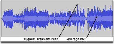
If you have special needs that are not analog audio signals, ie that are not CD, DVD, or streaming sources then, it would be interesting to know what such sources are. Presently I think you are making the mistake of attributing 0DbFS Full Scale as what consumer audio source equipment normally outputs , when they output 6.32 times less level, because the media contains the level. Seen as RMS here in light blue, the reason for this is to preserve dynamics and not have any possibility of distortion presented in consumer media.
The wise approach, where you are always in good hands, is to always do your best to match amplifier sensitivity to be close to consumer line level. Otherwise you are seemingly paying for output power that needs to have amplification to go from consumer line level to a greater level, when that is unnecessary and only adds distortion. That said here are occasional exceptions at each end like with tuners a Quad FM3 tuner with miserable 100mv output vs a Marantz ST50 with exceptional 940mv. But if its CD DVD or streaming service replay then they all stick to 0.316V nominal RMS. From that you can ascertain Voltage Peak (Vpk) as 0.447V and Voltage Peak to Peak (Vpp )as 0.894V
Attachments
Okay to clarify my use case:But you will always reach full output without a buffer
I like to build active speakers and have made a few. Some of them require a lot of power for the bottom end.
Now I am working on my own DSP for future projects. The DSP started mostly just for fun, but also because there is currently no product out there that can do what I want it to. Its progressing fine, but is currently using cheap aliexpress dac's until I finish the design of my own DAC modules.
These china DAC modules output 2Vrms SE signal directly from the pcm5102. When i finished my own DACS I'm shooting for Balanced output with 4Vrms.
I am also experimenting with different amplifier modules. Right now I have:
- MA5532 amp wich requires a 2Vrms SE input to reach full scale
- 3E TPA3255 amp which requires 4Vrms Bal input to reach full scale (I tried converting it to SE but got really loud pops and clicks on power up/down)
- IcePower 200AS2 which require 1.7Vrms Bal/SE input to reach full scale
- IcePower 1200AS2 whic require 3.5Vrms Bal7SE input to reach full scale.
So to make my life easier I wanted to build a input buffer (inspired by XRK's BTSB buffers) that I can put in front of these amps. This way I can set the buffers to ensure a 2Vrms SE input (which is what I have right now from my DSP) will give me full scale output of the amps without overloading the inputs. Then when I have finished my own dacs all I need to do is set the Gain correctly for 4Vrms bal input and all is good to go for a direct AB comparison.
I also had issues with my 3E amp. I can input v+ and gnd v- from my focusrite 2i2 with no problems, but when I use my china DACs i get random crackling noise which I was hoping this input buffer could get rid of (Pretty sure its not a GND loop issue).
Hope this clarifies why I am designing this buffer. Add to that that this is my first time designing anything with opamps, so thought this was a good exercise project before starting on my DAC's.
To understand this..If you have special needs that are not analog audio signals, ie that are not CD, DVD, or streaming sources then, it would be interesting to know what such sources are. Presently I think you are making the mistake of attributing 0DbFS Full Scale as what consumer audio source equipment normally outputs , when they output 6.32 times less level, because the media contains the level. Seen as RMS here in light blue, the reason for this is to preserve dynamics and not have any possibility of distortion presented in consumer media.
So you are saying if I buy lets say a wiim pro which has 2Vrms RCA outputs. at 0dB volume playing music it will only output 0.3Vrms? Or am I completely wrong here?
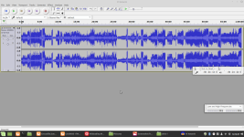
So I assume the y scale on those blue graphs are V? so the music signal does not go beyound 1V in each directions, but that would be 2Vp-p/0.7Vrms?
Is this at 0dBFS? This is soooo confusing xD
Reading the datasheet on page 4 www.ti.com/lit/ds/symlink/pcm5102a.pdf their output is 2.1V full scale , and its these last two words that are so important , that is being glossed over. Full Scale means there is only ONE circumstance in which full scale is reached which is with a Test CD that has copious warning if such a disc is owned or played. Normal CD's are 6.64 times less level than 2.1V RMS and 6.32 times less than 2V RMS . You needed to understand analog line levels before purchasing amplifiers that are as high as 11.07 times out of spec, but there is always opportunity to do so: https://en.wikipedia.org/wiki/Line_level
What to do, it suggests you need to add a power amplifier for voltage sake to make up this drastic mismatch, cough OMG just to feed the inputs , rather than only a buffer which is normally attending to current , and put up with the distortion it produces that can be very low , but never the less, there will be distortion added. A future project might approach amplifier sensitivity to always be consumer line level , where I think you should head toward.
What to do, it suggests you need to add a power amplifier for voltage sake to make up this drastic mismatch, cough OMG just to feed the inputs , rather than only a buffer which is normally attending to current , and put up with the distortion it produces that can be very low , but never the less, there will be distortion added. A future project might approach amplifier sensitivity to always be consumer line level , where I think you should head toward.
Last edited:
The 2V RMS only occurs with what is 0DbFS Full Scale , and streaming services would have no customers very quickly if they transmitted 0DbFsTo understand this..
So you are saying if I buy lets say a wiim pro which has 2Vrms RCA outputs. at 0dB volume playing music it will only output 0.3Vrms? Or am I completely wrong here?
So I assume the y scale on those blue graphs are V? so the music signal does not go beyound 1V in each directions, but that would be 2Vp-p/0.7Vrms?
Is this at 0dBFS? This is soooo confusing xD
The Wiim Pro is a streaming device it will comply with streaming service criteria called Loudness Units Full Scale , and to a degree you might be able to increase the providers level slightly , but levels are usually -14 LUFS , which is almost the same as 0.316V RMS.
With the level image Audacity explain it here: https://manual.audacityteam.org/man/audacity_waveform.html It describes to show wave forms that are RMS and the loudest sample in the group. It's indeed tempting to be automatically additive for the RMS figure as lower and upper portions, rather than what a negative duration attaining, being separate to a positive duration attaining is doing. I think the latter clarity, we can appreciate, as being the level in this case.
Okay @Chris Daly , I have read both links twice..
So let me try again if I understand it correctly:
Did I understand those points correctly?
So let me try again if I understand it correctly:
- So RCA connectors are typicaly made to output 2Vrms at 0dBFS
- XLR connectors are typically made to output 4Vrms at 0dBFS.
- In reality most linelevel content in consumer gear is at a maximum of -10dBV = 0.447Vp = 0.89Vpp = 0.31Vrms
- For pro level it is +4dBU = 1.736Vp = 3.472Vpp = 1.23Vrms
- The reason to keep signal levels so much lower than at 0dBFS is to ensure headroom for the much higher peaks found in music as shown by this graph from your link
- So I guees a pro level power amplifier with XLR inputs is designed to clip at a full 4Vrms sine wave. This will allow it to handle the 1.23Vrms music signal while maintaining headroom for transients?
Did I understand those points correctly?
Attachments
"XLR connectors are typically made to output 4Vrms at 0dBFS."
No. The genre of connector isn't linked to any electrical ouput 'standard'.
If you talk about pro gear ( studio), +4dbu ( 1.23V rms) is a calibration standard for typical 'vumeter' to ouput 0vu.
There is usually +20db headroom left on top of that ( as we have to deal with signals which have not seen any dynamic treatments) so line levels are usually defined as max output +24dbu.
You can find more ( some gear are able to output up to +27dbu, ever seen some able to go to +30dbu...) or less ( there is a trend to have gear in the +20dbu max ouput for 20years).
If we talk about DBfs ( digital scale) this means a dac will output +4dbu at -20dbfs if it have the capability to output +24dbu at max output level.
If it have max 20dbu output level then at -20dbfs it'll output 0dbu (0,7746 V rms).
It's in no way mandatory to stick to this, you can for example define an 'in house' standard to increase headroom along your chain or for other purpose.
In consummer world you could see XLR used because they allow symmetrical drive ( which can be (or not) balanced impedance), but the electrical 'standard' used is arbitrary choosen: 2v rms is often seen as max out level (+8dbu).
If you allow 20db headroom then the -20dbfs is then 0,1946v.
Last edited:
Correct , @DannerD3H , there is a very necessary provision for headroom, To make this work in our favor all we need do is to have voltage sensitivity of power amplifiers the same as consumer line level. We can then address what is missing namely current delivery. The best scenario is allowing the source component source impedance to be that same delivery. So we need to address attenuation as the non sexy subject it is , to be instead, as sexy as it really is.
Last edited:
Ooh my head hurts...
So there is basically no rules of what different outputs can deliver? It's free for the designer to choose..?
Okay so let's ask it differently. I have designed my DSP DAC to output 4vrms at 0dBFS through a balanced XLR connector with a opa1632 driving it with a +/-14v supply.
This would equal 14.26dBu/12dBV right?
Lets then say I want to connect this DAC to a icepower 1200as2. In its datasheet it says:
"Input sensitivity = 5Vp(3.5Vrms)"
"Maximum input voltage 8Vp(5.6Vrms)"
Then how do I figure out what gain is required for my 0dBFS to equal exactly clipping (3.5Vrms) in the 1200as2?
Isn't that then a gain of 0.875?
Or is the actual music level so much lower that I wouldn't even get close?
Sorry, but I'm so confused now xD
So clipping would appear at what Vpp?voltage sensitivity of power amplifiers the same as consumer line level.
Theoretically 0.894 Vpp , but realistically 1v Vpp allows what is nominal, some freedom to express.
- Home
- Source & Line
- Analog Line Level
- Understanding analog signal levels - RMS, P-P, SE, and Balanced