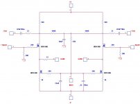
Okay, I originally decided on building a ccs-x-bosoz, but after looking at the schematic for the Aleph P1.7, I thought that they really weren't that different. So now I have been looking into the P1.7, but there are a few aspects in the design I just don't fully understand and I am hoping someone can fill me in.
First, what exactly are the rolls of Q15 and 18. At first I thought they were just current sources to keep the currents constant in Q16 and 19 in order to increase their linearity. But doesn't keeping the currents the same in each leg make the differential not work? I mean, if the current can't change, how does the voltage change?
Second, what are the rolls of R53, 56, 68, and 71?
Third, do R48 and 63 make this a susy amp?
Those are all the questions I have now, but I'm sure there will be more in the near future.
I understand that P1.7 has upper constant current sources (with Q15 & 18) and bottom constant current sinks (with Q17 & 20). By the way, the amount of source current is greater than the amount of sink current, so that the difference should flow through R52, 56, 68 and 71. As a consequence, we will see Vdc (Q-DC voltage) generated by R52 . . . 71.
The music signal controles Q16 & 19, musically changing the amount of current flowing through R52 . . . 71.
Regards
The music signal controles Q16 & 19, musically changing the amount of current flowing through R52 . . . 71.
Regards
sbear, I've been looking at that design lately... My proto looses the Q15 Q18 current sources in favor of 500 ohm Rs. And, my Q17 Q20 current sources are simpler with voltage ref from the drains of the gain transistors ala the ZenV7 fig 1. It's looking pretty good so far...
Let me see If I can answer a few of those Qs... Q15 & 18 are loads for the gain transistors along with being current sources. As the gain transistors are doing their thing, effectively changinig resistance with the audio signal, the Drain Voltage of Q15 & 18 floats around to maintain the same current through these guy's. The floating around will be the output signal...
I beleive R47, 48 & R62 63 could be used for susy operation but in this case instead of a feedback network to control gain they are being used to bias the gain transistor...
One of the reasons I like this design is the excellent SE to Bal conversion performance. Otherwise I would be playing with a BOSOZ or Aleph P 1.0 design...
had picked up veteran's boards few months back and now looking at bringing life to them....
excuse my ignorance, but the statement SE to balanced mean i supply with unbalanced to IN+, tie IN- to ground and still get balanced output?...
now to beat the volume control again... saw Nelson's comments about 3 options. the pot in the middle of the 610's... is that refering to the 2K VR if refering to kk-pcb (can't recall name, sorry) schematic? if so... can someone explain how that works ? If so, just need a log 2k single pot?... really don't want to open can of worms (cost at this point) on 4 deck attenuator. would likely resort to dual 10k panasonic pots initially on the input side.
I seem to remember Nelson saying something about distortion increasing with volume when a POT is placed in the middle of the 610's
-David
-David
Well, my observations from Pspice with my similar preamp show something similar... If I maintain output level, the simulated THD changes very little. I can vary the Gain pot between the sources, and maintain output level by manipulating the input level and distortion changes very little. If I raise the output level 2X with the gain cotrol, the simulated THD will probably double. If I raise the output level 2X by increasing input level, the sim'ed THD will increase maybe 30-40%. These numbers are close to what Pspice said, at about 3V and 6V output, with .35 and .7V input. And the pot at 40 and 110 ohms. But it's my variation, not exactly a 1.7. And of coarse the sim'ed THD numbers were all between 0.00047% and 0.0011% @1000Hz
I suppose I should accompany this with a thousand more words...
I suppose I should accompany this with a thousand more words...
Attachments
Well, Missing in that pic are the +80 Volt and -20 Volt rail. A Bias pot to set the 100mA per side Iq.. Assorted bypass and bulk caps.. And the R we speak of,,, probebly a 1K here... Oh yes, and FeedBack..😀 😀 😀
Well, probably very similar to the 1.7???
Well, probably very similar to the 1.7???
hmmm.. thanks for the info. looks like i'll leave that option alone. probably just go with dual stereo 10k pots for time being....
what size tranformer should i use... ps seems regulated. have handful of 57vct toroids, 280va (overkill/waste capacity wise). can get 80 rectified, will the ps take that and give 60 out?
what about unbalanced in and balanced out? if that case, can just have my 2-3 rca inputs to single stereo pot since i don't have balanced out dac at this time nor really plan to.
- Status
- Not open for further replies.
- Home
- Amplifiers
- Pass Labs
- Understanding Aleph P1.7