Can someone help me understand the Bias of the Marantz T1?
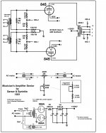
This first schematic is the "Musicians Amplifier" from Lilenthal Engineering website.
http://bit.ly/2OnrQnv
[IMG]
Now I understand how the Bias is set here, it's easy to see and understand.
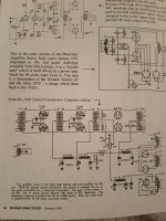
These next three schematic are from Sound Practices issue #1
The 1936 UTC amplifier is also pretty easy to see and understand the Bias set up. With the two pots coming off the LS-6 secondary.
[IMG]
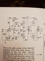
Next is the MARANTZ T1
[IMG]
This amplifier is where I get lost in understanding its Bias control.
It's my understanding that the Heaters on all three stages are fed from DC power supplies. Not shown here.
I've looked for a while now and this one schematic is pretty much all there is on the internet.
Be that as it may. How is the Bias adjusted here? Or is it fixed? Or might it be something that is adjustable, its just that the part of the circuit where Bias control is set is not shown here, so we have to imagine a control circuit elsewhere?
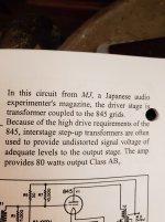
And lastly is a circuit from MJ magazine with the 845's being driven from a single Interstage transformer.
Again same question.
How would Bias be adjusted here? It looks like there are two separate filament transformers here.
And I'm assuming that the Bias section just isn't shown.
The power supply section is obviously missing so again the Bias would probably be a part of that circuit.
I'm wondering if a Bias scheme similar to the one used in the "Musicians Amplifier" would be applicable here ???
This first schematic is the "Musicians Amplifier" from Lilenthal Engineering website.
http://bit.ly/2OnrQnv
[IMG]
Now I understand how the Bias is set here, it's easy to see and understand.
These next three schematic are from Sound Practices issue #1
The 1936 UTC amplifier is also pretty easy to see and understand the Bias set up. With the two pots coming off the LS-6 secondary.
[IMG]
Next is the MARANTZ T1
[IMG]
This amplifier is where I get lost in understanding its Bias control.
It's my understanding that the Heaters on all three stages are fed from DC power supplies. Not shown here.
I've looked for a while now and this one schematic is pretty much all there is on the internet.
Be that as it may. How is the Bias adjusted here? Or is it fixed? Or might it be something that is adjustable, its just that the part of the circuit where Bias control is set is not shown here, so we have to imagine a control circuit elsewhere?
And lastly is a circuit from MJ magazine with the 845's being driven from a single Interstage transformer.
Again same question.
How would Bias be adjusted here? It looks like there are two separate filament transformers here.
And I'm assuming that the Bias section just isn't shown.
The power supply section is obviously missing so again the Bias would probably be a part of that circuit.
I'm wondering if a Bias scheme similar to the one used in the "Musicians Amplifier" would be applicable here ???
Attachments
Last edited:
The Marantz T1 is an interesting circuit. But it's NOT the amp I would have built.
First of all I would exchange the UTC LS-6L4 for a FREED QGA-42 output transformer. The Freed is rated for 100 watts @ 5K ohms.
Secondly I would not use 845 for the HV rectifiers. 836, or 866A or even solid state.
Third bump the B+ up to 1100 or 1200 volts so 80 to 100 watts out is feasable.
Of course that means beefing up the cap ratings too.
Left most schematic
915V plate, 85V drop across the self bias resistors
A 500 Ohm bias rheostat resistor and 200 Ohm balance resistor allows setting of the total current, and balance, respectively of the two 845s. There are two more resistors (*) to get the total resistance of the self bias circuit so the range of current is correct for the actual B+ voltage.
Next schematic (UTC)
Adjustable Individual Fixed Grid Bias.
Unfortunately nobody lived to tell of the bias adjustment. The two 1/4 inch jacks are for plate current meters, but each one has the 900V to 1000V on each jack sleeve and nut (how shocking). You need to enclose those connections away from hands, and the meter leads too.
Also, you need to be sure the 83 mercury vapor rectifier for the negative grid bias is powered and up and running before the B+ comes up, or you get meltdown of the 845s. Actually, the 83 filament secondary and negative voltage secondary are on the same transformer (not good, supposed to warm up mercury vapor filaments before the plates are rectifying).
Marantz T1
The two 1.5k Ohm self bias resistors and 22 Ohm current sense resistors (TP 5 and 6), are the self bias network. Each series network of 1.5k and 22 Ohm are bypassed by a capacitor.
Individual self bias, nice.
The next schematic is simply the old print, and the first schematic is the same Senior Amp.
The last schematic is incomplete, and so no conclusion is possible.
I favor using individual self bias networks, (resistor and bypass cap). And that requires individual filament supplies.
I recommend DC filaments.
With AC filaments you get 2x line frequency sidebands on each musical note / tone.
That is true, even if you balance out the hum (like no hum when there is no music playing).
Do you really need 80 to 100 Watts?
This is a dangerous and very demanding build.
Safety first.
"You should make it as simple as possible, but no simpler" - Albert Einstein

Last edited:
6A3sUMMER The last schematic is incomplete said:Yes I posted the other schematics for reference. I'm hoping someone can help me extrapolate what the powersupply / Bias supply would work for that circuit.
Use the powersupply from Sakuma's amp with the 6J5 driver circuit.
The Bias circuit is what I was looking for.
Probably sub out the rectifiers with 836 or 866A's
And maybe use 6BL7GTA instead of 6BX7 ??? A little R&D needed there.
I had Phil at Heyboer make me the interstage transformer labeled NC-9 it's 5K to 20K ohms ct.
And use FREED QGA-42 output transformer. 5K ohms at 100 watts.
Attachments

Last edited:
Your post # 6 has an 8 uf capacitor to provide all the plate current for two 845 tubes.
8uF is 995 Ohms at 20 Hz.
You will only be able to operate in class A on the output stage. Otherwise, the 8uF cap will cause the B+ to drag down, and clip the output stage.
You should use more capacitance than 8uf.
As to bias circuits, first decide whether you want fixed adjustable bias, or self bias.
For interstage driver secondaries that do not have two separate windings, and using fixed bias, you can not individually adjust the current in the two 845 tubes.
Individual filament supplies, individual self bias resistors, and individual bypass caps . . .
many tubes will have similar plate currents. And self bias helps prevent thermal run-away.
To determine the bias voltage, use the 845 tube curves, and determine the plate to filament volts you want to use, and the current you want to run at.
Your bias circuit will need to provide that voltage (fixed or self bais).
Last edited:
Just my personal opinion of course, and not a criticism, but 5K Ohms anode-to-anode is a poor choice for *any* of the 50-watter valves, even the least stringent type 845. Twice that puts the valves into the linear category and twice that again gets into the truly magic realm of great linearity and decent loudspeaker damping. Driving an actual loudspeaker is, after all, the goal.
These historical designs are interesting as historical items, but aren't even remotely carved into stone tablets and carried down from mountaintops. Push-pull type 845s is an exciting *new* thing, to be made the best of. Rant mode off, sorry.
All good fortune,
Chris
These historical designs are interesting as historical items, but aren't even remotely carved into stone tablets and carried down from mountaintops. Push-pull type 845s is an exciting *new* thing, to be made the best of. Rant mode off, sorry.
All good fortune,
Chris
Well I did manage to build the Musicians Amplifier. You are correct it's very dangerous.
I love the looks of it! That is a work of art! Supernice build!
Please post some more pictures of it as some inspiration and motivation for our future projects!

Can someone explain the Bias here? The 100 ohm pots these are Hum pot adjustment I take it? And the Bias is Fixed, and is it set with the 2400 ohm resistors through the meters then to ground? R15 & R17
And the filament center taps are just left floating?
This type of bias is called cathode bias or self bias. Current through the 2k4 Ohm pots (and the meters) drops enough voltage to bias the valves about 150 Volts. Filament winding center taps aren't used with this kind of hum pots.
All good fortune,
Chris
All good fortune,
Chris
Good website with a write up of the original 845 Musicians Amplifier by Sarser & Sprinkle
https://www.americanradiohistory.com/Archive-Audio/50s/Audio-Anthology-1953.pdf
https://www.americanradiohistory.com/Archive-Audio/50s/Audio-Anthology-1953.pdf
In post # 10, I thought the bypass capacitor of 12 uF was too small for the 2.4k self bias resistor and the 845 tube. So I decided to find the amount of capacitance that I would use there.
Suppose the plate load was 5k Ohms and 40 Henry inductance. 40 H is 5000 Ohms at 20 Hz.
The 845 plate sees 2500 Ohms at 20 Hz.
The 845 u = 5.3, and its transconductance = 3100 micromhos.
The “cathode” impedance at 20 Hz is 2500 Ohms/(u + 1) in series with 1/3100umhos.
2500/6.3 = 397 Ohms. 1/3100umhos = 323 Ohms. 397 + 323 = 720 Ohms
2400 Ohms in parallel with 720 Ohms is 554 Ohms.
When the difference of the ac voltage at the “cathode” is different when the bias resistor is unbypassed (unity) versus bypassed (0.1 x unity), the frequency response will be -1 dB there.
If we want the frequency response due to the bypass cap to be -1 dB at 20 Hz, we need the capacitive reactance to be 0.1 x 554 Ohms = 55 Ohms.
Capacitive reactance, Xc = 1/(2 * pi * f * c)
1/c = 55 * 2 * pi * 20 Hz.
c = 145 uf. We can use a 150 or 200 uF cap there and be - 1dB @ 20 Hz.
In my opinion, a 12uF bypass cap there would cause severe low frequency roll off.
Why your mileage may vary:
If the plate load was different than 5000 Ohms and the inductance was different than 40H, the bypass capacitor would need to be adjusted to a different value in order to be -1 dB at 20 Hz.
Looking at Meter 1 and Meter 2.
Any idea are these set up as volt meters, or Milliamp meters?
I know they have a red-green-red face and don't give an actual reading.
The meters are in parallel with the .7 Ohm resistors to ground.
I know in the Musicians amplifier circuit the metering runs about 100 to 140 ma per tube.

Any idea are these set up as volt meters, or Milliamp meters?
I know they have a red-green-red face and don't give an actual reading.
The meters are in parallel with the .7 Ohm resistors to ground.
I know in the Musicians amplifier circuit the metering runs about 100 to 140 ma per tube.
- Home
- Amplifiers
- Tubes / Valves
- Understanding 845 PP Bias