Baaad Papa!
keeping Greedy Boyz in paralyzing dilemma
Nah... We just watch the bees in the meantime.... 😛
Good news BTW. A Pass article is always a good read 🙂
I thought a line input Tx would be better but mine have single windings on primary 🙁
6110K.
http://www.jensen-transformers.com/datashts/6110kb.pdf
edit: maybe by inverting one of the secondaries, it'll work...but still the gain will have to be increased...or use a couple of Tx for each amp. I'll think further.
re-edit: this Tx are better suited for a bridged amp. Just thinking out loud...sorry.
Last edited:
most probably too high impedance , even if you use two per channel
however - you can try ......
however - you can try ......
first - you need 1:1 ratio from input to each gate
second - you need lowest possible impedance xformer , to have broadest bandwidth ;
so , in case of classic 600:600 repeater (two windings on each side ) , both conditions are fulfilled
in case of , say , 10K:10K ( center tapped ) xformer , first condition is fulfilled , but bandwidth will suffer ..... due to greater Rdc of windings , and also due to greater stray capacitances
O.K. I build the skeleton Nelson showed with the beamer at Burning Amp Festival.
- with the two voltages shown for the complementary Acronman SITs 8.0V and 7.4V I had a much too high bias current around 2.6A or more, I switched off very quickly….😀
- with 11.9V for the 2SJ28 and 8,35V for the 2SK82 I got 1.2A and only a small offset of 8-10mV. Of course changing when the SITs heated up.
That looked good….
but there was only heavy hum coming out of my speaker….🙄
Two possible reasons the Edcor XS4400 has no good place, or the two small PSU are not good enough in hum suppression, the data sheet speaks of less than 50mV.
So it seems that the SITs are less matched or similar to Nelsons pair than we thought.
I think you should go for 15V for the supplementary PSUs to have enough headroom for SIT variations and it must be more quiet than mine.
Now I have done my duty and relax until Nelsons article will be published….🙂🙂🙂
I will try to better the small PSU in the way
Dzius did…..look here…..
http://www.diyaudio.com/forums/pass-labs/233057-sit-variations.html#post3433887
Dzius did…..look here…..
http://www.diyaudio.com/forums/pass-labs/233057-sit-variations.html#post3433887
Two things, the SITs are sensitive to supply ripple due to the low Drain
resistance (triode...) You need a low noise regulated supply.
Also, keep in mind that the Edcors use steel cores, better suited to higher
level signals than the 50% Nickel, so you will see some differences there.
😎
resistance (triode...) You need a low noise regulated supply.
Also, keep in mind that the Edcors use steel cores, better suited to higher
level signals than the 50% Nickel, so you will see some differences there.
😎
I don't know why but the "low Drain resistance" phrase reminded me of Bench's Inverted Triode and how workable it might be with a SIT.
Interesting article which by [my] analogy implied that the power output port of an N-channel SIT may be its gate.I don't know why but the "low Drain resistance" phrase reminded me of Bench's Inverted Triode and how workable it might be with a SIT.
..... You need a low noise regulated supply.
..........
😎
for the gate voltage or for the main PSU with it +- 24 V.....or both.....?
😉
Hi nicoh58!
The hum was so heavy that I did not want to hear music......
The DC situation is good. Maybe I will try 9V batteries, but I have to change the SIT that needs 11.xxV.
Simplest thing is to wait for Nelson's article....🙂
The hum was so heavy that I did not want to hear music......
The DC situation is good. Maybe I will try 9V batteries, but I have to change the SIT that needs 11.xxV.
Simplest thing is to wait for Nelson's article....🙂
Hi nicoh58!
The hum was so heavy that I did not want to hear music......
The DC situation is good. Maybe I will try 9V batteries, but I have to change the SIT that needs 11.xxV.
Simplest thing is to wait for Nelson's article....🙂
In the interim, one may speculate about these hypothetical solution.
- Sample the ripple at the source of the SIT.
- Feed this ripple [with the music signal] to the gate of the SIT to get ripple cancellation. My earlier post suggesting the use of a rheostat to control drain current fits this description.
- If the ripple at the positive rail is made to be out of phase with that of the negative rail, and both ripples have equal amplitudes, then auto cancellation will happen at the opposed drain output port.
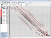
I have measured as good as I could ten SJ28 and nine K82, so I dare to say that at 1,3A for instance the working point of Papas Push-Pull they differ around 3-4V
There is one SJ28 KF instead of KE but it is not outside…….
As far as I remember the KE and KF was a pinch Off voltage and this marking seems not very important for the matching of Iron AmP or the SONY AmP…..
Of course my input data I choose for the tracer are self-made without any deeper knowledge….🙁
I am always happy to see at least a curve…..
the picture shows in red the SJ28 and in black the SK82..
Horizontal axis the gate voltage, vertical axis the current in mA
So you see that it is possible to find closer pairs!
😀
Attachments
Last edited:
- Status
- Not open for further replies.
- Home
- Amplifiers
- Pass Labs
- Ultrasimple SIT PP amp from BAF , or SIT Beast with a Thousand PSUs