....screen is operated at a lower voltage than the plate. Looks to me the belief is unique to many here on DIY....
Not unique to "here". You find it all over the Web.
It is literally true for True Tetrodes. NOT all 4-electrode tubes are True Tetrodes. Small true tetrodes stopped at type '24. Large ones persisted: 4,000 Volts plate and 400V screen, and a big suck-off if plate fell below screen. Beam power tetrodes are NOT True Tetrodes.
A Pentode (even without an actual G3) suppresses the flop-over from plate to screen down to around 1/5th of screen voltage.
The Frankland interview does not discuss relative P/G2 voltages, only "excessive".
There are good tube-design reasons to favor an aggressive screen which will suck at low voltage. There are good amp-design reasons to favor a tube which can be tamed with screen near plate supply.
I should have used a better way at describing the problem. I didn’t mean to infer that something like an 807 could be run at 700 volts on both plate & screen. And survive for long.
What I tried to point out are the many questions of running the screen a few volts lower than the plate in a common 250V B+ application. That kind of question does appear here on DIY from time to time. All in spite of the evidence of the millions of common radios built & used from the late 30s until the early 60s. In those the screen was almost always at a higher B+ than the plate due to IR drop across the OPT. Very ordinary kinds of amplifiers that were anything but HIFI, even by the standards of the day.
I’m familiar with Bill Kleronomos’s article in Sound Practices. I subscribed to the entire series of that magazine. It contained quite a few good articles. But some are faulted. I had some correspondence with Joe Roberts, in one note he indicated that some of the authors had trouble getting their amplifier to work.
Bill K’s amp is not a Williamson as is indicated. Williamson did not use Schade NFB as appears in this amp. Schade FB brings with it problems, often not recognized on DIY. The result is a load more difficult for the driver to work into. So where it looks like the driver 6SN7 in this example need drive only the plate Rl of 100 K & a FB of 100K, the reality is very different. In this cct the FB R looks like 100K/ Gain of output tube. With these kinds of toobs gains of 10 to 20 are typical, simply GmRl. So I would reject the results here out of hand. A proper test needs to check the output stage in isolation, remove as many variables as possible.
Same for the combination of driver & output tube, testing in SE simplifies that.
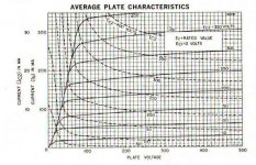
Lowering the screen voltage of the power tube drops the entire plate family of curves & requires a higher load impedance. And control grid voltage needs to be dropped, all translates to lower output power capability. For those who read the data sheets those facts also obvious.
The Pappas/Frankland Interview is all too true, many builders today do not respect the tube manufacturers published specification.
And Pappas reminds me of the Theorems of Pappus & Guldinas, an pair of ancient mathematicians’. Who devised a slick way of determining the volume of for example a toroid.😀
What I tried to point out are the many questions of running the screen a few volts lower than the plate in a common 250V B+ application. That kind of question does appear here on DIY from time to time. All in spite of the evidence of the millions of common radios built & used from the late 30s until the early 60s. In those the screen was almost always at a higher B+ than the plate due to IR drop across the OPT. Very ordinary kinds of amplifiers that were anything but HIFI, even by the standards of the day.
I’m familiar with Bill Kleronomos’s article in Sound Practices. I subscribed to the entire series of that magazine. It contained quite a few good articles. But some are faulted. I had some correspondence with Joe Roberts, in one note he indicated that some of the authors had trouble getting their amplifier to work.
Bill K’s amp is not a Williamson as is indicated. Williamson did not use Schade NFB as appears in this amp. Schade FB brings with it problems, often not recognized on DIY. The result is a load more difficult for the driver to work into. So where it looks like the driver 6SN7 in this example need drive only the plate Rl of 100 K & a FB of 100K, the reality is very different. In this cct the FB R looks like 100K/ Gain of output tube. With these kinds of toobs gains of 10 to 20 are typical, simply GmRl. So I would reject the results here out of hand. A proper test needs to check the output stage in isolation, remove as many variables as possible.
Same for the combination of driver & output tube, testing in SE simplifies that.
Lowering the screen voltage of the power tube drops the entire plate family of curves & requires a higher load impedance. And control grid voltage needs to be dropped, all translates to lower output power capability. For those who read the data sheets those facts also obvious.
The Pappas/Frankland Interview is all too true, many builders today do not respect the tube manufacturers published specification.
And Pappas reminds me of the Theorems of Pappus & Guldinas, an pair of ancient mathematicians’. Who devised a slick way of determining the volume of for example a toroid.😀
Attachments

Hi, the reason is, or better to say was, I have some BHEL34 boards and was thinking to use one of them with a power trafo I have (it gives around 500Vdc): the reason to drop screens was safety.But I also don't know the reason for his desire to lower the g2 bias on an EL34 in UL, so....
This evening I simulated the other circuit (23% a-g1 + 23% UL feedback) with EL34 and it's superior to that one in terms of power and DF, So no more need to drop it. I'll use a pair of BHEL34 boards for a 6V6 amp using EL84 trafos.
 Copyrighted material removed by moderation. Copyrighted material may not be posted to the forum without the express permission of the copyright holder. See rule 9.
I certainly found that Williamson amp driver stage distortion was noticeably lower with a 6SN7 than the commonly used 12AU7, although tube rolling was needed for either tube if the aim was to get to the best of what one has available. Wright (1961) claimed performance improvements from altering the bias setup of the driver stage, but I couldn't replicate any distortion improvement (as the Williamson does not push the driver to cutoff and saturation extremes, and so just finds a nice region to operate in) - Kleronomos may have been influenced a bit by Wright's claims. If I get the chance I will try a 12BH7, although it really is the output stage where the largest distortion contribution occurs.
Kleronomos' use of local output stage anode-to-grid feedback (schade) possibly came from looking at RCA manuals like 1960 RC-20 on page 411. I haven't tried to see if some blend of that form of feedback can provide a net benefit for the base Williamson amp. Williamson's amp doesn't get in to driver clipping, or class AB1, or UL, or zener firmed UL, or have to work with the loading from the local feedback that Kleronomos uses, so imho it is not appropriate to make apples-to-apples comparisons on what driver provides better THD performance other than to try in separate amps.
Tube rolling output tubes has been shown to often exhibit a range of distortion performance, and Kleronomos describes similar observations, along with some benefit from adding common cathode resistance for fixed bias configurations.
Ciao, Tim
Last edited:
- Home
- Amplifiers
- Tubes / Valves
- Ultralinear with zener on the screen