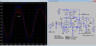
I was looking for examples of EL86 amplifiers, and have come across this interesting candidate.
It is credited to a person called 'lagarto', and is partially described here ...
EL86SE
It has the whiff of Japanese innovation about it, and I'm sure it could work, but could it match a transformer with a UL tap?
If it is an effective alternative, then there are lots of tubes with lower voltage rated screens that could surely benefit from this approach?
It looks deceptively simple. What are the purposes of the 100uF from the primary of the OPT to the EL86 cathode? And the 47R?
Attachments
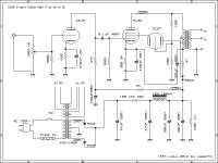
What a horrible circuit.
The 47R, 100u and 470u act as decoupling for the HT supply.
It cannot be used in UL mode as the triode is a regulator and will defeat the objective.
Nothing wrong with a zenner diode instead and then it will work in UL mode.
The 47R, 100u and 470u act as decoupling for the HT supply.
It cannot be used in UL mode as the triode is a regulator and will defeat the objective.
Nothing wrong with a zenner diode instead and then it will work in UL mode.
That 100uF capacitor used there is normally for hum cancelling , but with that 47ohm is also some audio feedback .
In my opinion you are lazy if you can't do it right without needing such circuits .
Ultralinear using a tube is an interesting idea . But if you have acces to the primary interleaved windings , finding the middle for normal UL is not a problem .
In my opinion you are lazy if you can't do it right without needing such circuits .
Ultralinear using a tube is an interesting idea . But if you have acces to the primary interleaved windings , finding the middle for normal UL is not a problem .
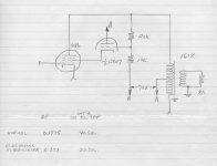
IIRC Mona posted a similar circuit but with a BJT to create the virtual UL tap.
IIRC I reposted his circuit in my "Baby Huey enters into puberty" thread.
IIRC I reposted his circuit in my "Baby Huey enters into puberty" thread.
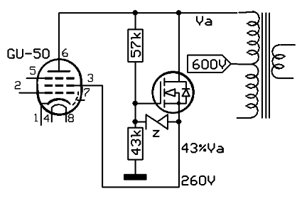
Yes you can take some combination of HT, GND and output plate voltage, and buffer it as the screen takes current. This could be a transistor, mosfet or cathode follower. You can also lower the screen voltage that way and run the HT higher.
Baudoin0, Zintolo, is it capable of delivering good results, in your opinions?
It has an elegance about it.
It has an elegance about it.
Since in UL mode, the screen voltage is about the same as plate, hence the screen driver which is a cathode follower, the anode voltage must be raised so it has sufficient headroom swing for full output esp. in triode mode, the screen swings as much as anode. In the post #1, the ecap and resistor is just trying to isolate the driver plate supply from output tube. As separate HT supply these are not needed.
Attachments
Last edited:
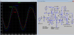
Many toobz such as the 6Y6, 6W6 & TV sweep tubes operate well at lower screen volts than plate volts. Just need to attenuate the FB swing to the screen so that it does not go too low. Good examples of an amps built that way used PP 6146s. But the screens in that case were driven by a tertiary wdg on the OPT. Could have been done with CFs driving the screens just as well. H-K insulation failure is a problem for the CFs,🙂
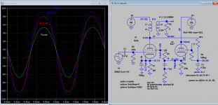
Ok too much feedback for 6146b. Now attenuated the driver swing by 10 times and use 20K OT, 200V screen and 750V HT, 400V driver, got very reasonable result. Attached sim file for those who wants to persuade further and learning.
Attachments
You can find the schematic I was talking about here:
Baby Huey enters into puberty: 6550 KT88 possibly GU50?
Baby Huey enters into puberty: 6550 KT88 possibly GU50?
A question about the implementation of the circuit in the original post: How would the heater-cathode insulation max voltage limit be satisfied? The swing on the cathode of the G2 driver due to the audio signal to the OPT is going to be 200V or so, isn't it? Or is the only consideration the DC potential difference?
The grid will be at 110 V with no signal. At full power it will swing between about 25 V (if Va could go as low as 50 V) and 220 V (if Va could go as high as 440 V). The cathode voltages will be a bit higher. If you would lift the filament supply to 75Vdc, I think it all will stay within the limits for the maximum cathode to heater voltages of the 6CG7.
The schematic in post #1 is showing all filament supplies as not grounded. I did see this being done for tubes of which the cathode sits at high(er) dc potentials (the capacitive coupling in the power transformer than is 'enough'). But I would think that the other tubes would be happier when their filament supplies were grounded.
The schematic in post #1 is showing all filament supplies as not grounded. I did see this being done for tubes of which the cathode sits at high(er) dc potentials (the capacitive coupling in the power transformer than is 'enough'). But I would think that the other tubes would be happier when their filament supplies were grounded.
Thanks for the analysis! I just noticed the heater cathode insulation is rated +/- 200V from the datasheet, so maybe that is something special the 6CG7 brings to the party.
I have some old radios and PAs that just have a capacitor from the last tube heater to ground so there is some reference, which seems to be effective.
Should be possible to try this idea with an existing UL transformer, comparing the two approaches. Something to try during the dark cold gloomy never-ending winter nights ...
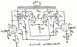
Ultra-linear us not all that linear as it sounds, since grid2 does not have the same transfer factor (power law) as grid 1. So effectively corrupting the N Fdbk.
By comparing the output with the input signal, one can control the grid2 to get much better linear gain using active-ultralinear.
By comparing the output with the input signal, one can control the grid2 to get much better linear gain using active-ultralinear.
Attachments
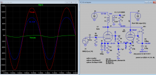
op- it´s flawed idea , because inductors can generate voltages above power supply.
any follower obviously can´t do that ........you here literally skipping every positive halfwave
any follower obviously can´t do that ........you here literally skipping every positive halfwave
Last edited:
I think you have a point. But if you mean that it will skip every positive halfwave completely, than I disagree.
The anode of the 6CG7 stays at 230 V. It's grid swings between 25 and 220 V. So only a part of the positive halfwave would get impared by the anode to cathode voltage of the 6CG7 getting too low.
So the solution probably is to feed the 6CG7 with a higher voltage than 230 V (something koonw already did).
- Home
- Amplifiers
- Tubes / Valves
- Ultralinear SE amp with no UL tap