MikeB,
sorry, I was not very careful, when I saw the schematics. I don't want to use cascode connection. I found that it sounds sharply in the HF region. Somebody feels it as clean sound, but I don't like it.
So, I try to use double differential, with low overall feedback. Something like Mark Levinson, but more simple. As I remember You try something same few weeks before...
sajti
MikeB said:And phaseshifts, the do not look too good.
Mike
Try to reduce the open loop gain. I think, that increasing the emitter resistors in the input stage helps to do it.
sajti
MikeB said:Hi Jan !
I checked your suggestion, i replaced the 1.87 voltage with 3 diodes
in series fed with 15k, (I had no adequate LED-model)
there are only subtile changes.
I checked with different closedloopgains, with gain of 26 results
in acsweep look identical, with gain 1:10 the acsweep gets critical,
but no oscillation yet. I decreased timestep from 10ns to 2ns to
be sure.
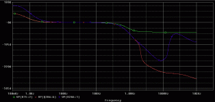
Attached is acsweep, blue is output before coil, green left base
of diffamp, red right base of diffamp. Feedback keeps always
below input, so should be safe.
Mike
Looks pretty good to me. But to be sure, you should put couple of ohms in parallell with that output choke. As it is, it start to roll off the output to the 4 ohms load above 350kHz or so. I'm not sure what that does, and I can't think of a good reason (engineering wise) to do it, but it is customary and it may have an influence. Then again, you may be the first to prove that "what everybody does" is just so much BS...😉 . Sheep following and all that.
OTOH, there may be a reason once you get into complex xover networks. Anyone?
Jan Didden
Hi sajti !
This is folded cascode, not cascoded vas, or do you meant the FC ?
I did not observe/hear sharp sound, but you're right, this could be
about taste... (it does sound clean)
About the phaseshifts, i am not sure...
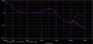
I took the phasehifts at diffampoutput (currents because of FC),
they stay in phase up to 100mhz... Don't know why...
The +180 is because they are inverted/mirrored. (left to right)
Attached the phasehifts...
Mike
Attachments
It is possible! You need to use very fast transistors in the input stage (very fast as in GHz+ ft) with copious amounts of emitter degeneration and a MOSFET or otherwise very fast output stage.MikeB said:...it seems impossible to get a "standard" topology stable
without feedbackcompensation...
MikeB said:Hi sajti !
This is folded cascode, not cascoded vas, or do you meant the FC ?
I did not observe/hear sharp sound, but you're right, this could be
about taste... (it does sound clean)
About the phaseshifts, i am not sure...
I took the phasehifts at diffampoutput (currents because of FC),
they stay in phase up to 100mhz... Don't know why...
The +180 is because they are inverted/mirrored. (left to right)
Attached the phasehifts...
Mike
When I built cascode connected amplifier, I feel, that it very clean. After some listening I found that it "too clear". Than I started to find something about it. Than I found an article about this effect. The very heavy load of the bottom device can results this sound. The upper transistor has very low input impedance, and it provide this heavy load.
I will try the double differential amplifier in the next 1-2 weeks. I will report the results. I don't think that we need very fast amplifier topology, if we not use large overall feedback.
sajti
MikeB said:
they stay in phase up to 100mhz... Don't know why...
Oops, of course they do... 🙄
Mike
sajti said:
Than I found an article about this effect. The very heavy load of the bottom device can results this sound. The upper transistor has very low input impedance, and it provide this heavy load.
I will try the double differential amplifier in the next 1-2 weeks. I will report the results. I don't think that we need very fast amplifier topology, if we not use large overall feedback.
sajti
But you told me that for the cascoded vas ?

The other topology i posted a few weeks ago sounds very good,
just not outstanding, too "natural"/soft for my taste.
Mike
MikeB said:
But you told me that for the cascoded vas ?
The other topology i posted a few weeks ago sounds very good,
just not outstanding, too "natural"/soft for my taste.
Mike
It can be true for any cascode connection. The common base stage has the low input impedance. Doesn't matter where we use it. But if You satisfied with this amplifier, why not? I don't want to let You, to leave this design.
sajti
Ah, i understand !
Okay, now i will try to find out why this amp does not oscillate,
according to phaseshifts it should oscillate with 3.6mhz, but it
does not, at least not in sims...
Mike
Okay, now i will try to find out why this amp does not oscillate,
according to phaseshifts it should oscillate with 3.6mhz, but it
does not, at least not in sims...
Mike
Maybe the open loop gain is less than the closed loop, at 3.6MHz. For oscillation You need sufficient gain.
sajti
sajti
Yes, that's the strange thing, at 3.6Mhz it still outputs ~1v with input
of 0.3v. So it's far above unitygain.
But phaseshifts are 180° at diffampinput... I will look again...
Yes, openloopgain is far below closed loop, but is that enough ?
And if yes, shouldn't it be below unitygain ?
Mike
of 0.3v. So it's far above unitygain.
But phaseshifts are 180° at diffampinput... I will look again...
Yes, openloopgain is far below closed loop, but is that enough ?
And if yes, shouldn't it be below unitygain ?
Mike
MikeB said:Yes, that's the strange thing, at 3.6Mhz it still outputs ~1v with input
of 0.3v. So it's far above unitygain.
But phaseshifts are 180° at diffampinput... I will look again...
Yes, openloopgain is far below closed loop, but is that enough ?
And if yes, shouldn't it be below unitygain ?
Mike
If the open loop gain is less than the closed, there will be no oscillation. The open loop gain can be higher than 1, but it must be less than the closed loop gain.
sajti
Okay, understood !
I just made sims with inputsignal of 3.6mhz...
The 2 signals are 180° phasehifted, but due to the absence of
the feedbackcap (is it lead or lag ? i swap them always), closedloopgain
was heavily increased at this frequency because of the inputcapacity
of the bjt on feedbackside of diffamp...
Funny way to stabilize an amp, but maybe not state of the art ?
Increasing closedloopgain above openloopgain at resonancefreq.... 😀
At least the choice of caps is not difficult with this amp !
So this amp is "accidently" stable, but as doubledarlington really not fast
with the 180°-freq at 3.6mhz... (but still amplifying at this freq !)
So, no miracle amp at all... Pity... But interesting !
Now i will try with "correct" feedbackcompensation, and check how it sounds then...
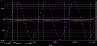
I attached a shot of sims at 3.6Mhz. Pink is output, blue is input
(Left side of diffamp-base), yellow is feedbacksignal (Right side of diffamp-base)
Mike
Attachments
I tried many kind of compensation. Finally I found, that series RC network is the best. I found, that the pole frequency must be over 20kHz (preferably 40kHz or higher). The R must be as small to reduce the amount of open loop gain to the amount of closed loop gain, over the pole frequency.
But I don't know where should you put this network in this amplifier.
Another good solution can be the capacitor from the VAS, to the feedback point (base of the second MPSA).
sajti
But I don't know where should you put this network in this amplifier.
Another good solution can be the capacitor from the VAS, to the feedback point (base of the second MPSA).
sajti
I saw the picture You attached. I see the phase shift between the input, and the feedback signals. But with normal working, the levels must be same. Due the feedback level is much lower, this amplifier has much lower gain than the closed...
sajti
sajti
MikeB said:Yes, that's the strange thing, at 3.6Mhz it still outputs ~1v with input
of 0.3v. So it's far above unitygain.
But phaseshifts are 180° at diffampinput... I will look again...
Yes, openloopgain is far below closed loop, but is that enough ?
And if yes, shouldn't it be below unitygain ?
Mike
Mike, where do you measure the output, at the load or at the amp side of the choke?
Jan Didden
Hi !
Jan, i measured at the ampside of the outputchoke...
Sajti, yes, the levels should be nearly identical, but at this high freq
the inputcapacitance of the feedbacksidebjt seems to push down
the level. That's what i've meant with increasing closedloopgain.
But even with cap across the 22k it does not oscillate...
In audiofreqband this effect is not visible yet.
Mike
For final confusion...
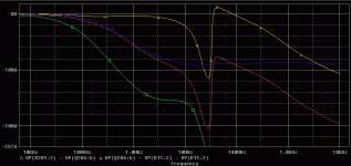
I sim'd with 33pF across the 22k in feedback, attached are the
resulting phasehifts.
Green is output, red is feedback, blue is input and yellow difference
between phaseshifts of input and feedback.
Now it never reaches 180° ??? This circuit drives me crazy !
Mike
I sim'd with 33pF across the 22k in feedback, attached are the
resulting phasehifts.
Green is output, red is feedback, blue is input and yellow difference
between phaseshifts of input and feedback.
Now it never reaches 180° ??? This circuit drives me crazy !
Mike
Attachments
- Status
- Not open for further replies.
- Home
- Amplifiers
- Solid State
- Ultrafast NoCap-ClassAB


