Is it safe to use ultra linear output transformers PP 30W/25W for a single ended very low power project? I have several PP amplifiers, and never could feel a sound from a Single Ended amp.
I'm a little confused because some people already told me that I have to take into account the saturation and air gap.
I would be very happy because I have several EL34 valves and PP transformers left here at home.
If this is possible, how much power I could build this Single Ended amp using Ultra linear transformer 25W/30W PP?
Is it safe to use ultra linear output transformers PP 30W/25W for a single ended very low power project?
some people already told me that I have to take into account the saturation and air gap.
Push-pull output transformers are not intended to have a net DC flowing.
The DC in each half of the primary must be equal and opposite to cancel the flux.
Transformers for single-ended amplifiers are very different, and have a gap designed in.
Long time listener, first time poster.
Please correct me if I am wrong.
If a C-core PP OPT is used and it is strapped simply, Wouldn't you be able to put some paper between the cores then re strap them?
Just a sheet of paper or 2. (I know its not going to be tuned to any particular current)
If you wanted to tune it could you put it in an amp, load with an array of light globes.
I think some EI PP OPT this cam be dome to, but only if the Es and Is are not interleaved.
Its just been something that I have been thinking about, because I often see comments like "SE and PP OPT are wound differently" when I do not think they are. I think they are constructed differently, allowing for the air gap.
FYI I have hand wound my own set of PP OPT about 20 years ago, I remember reading heaps of theory, but most has fallen off the end.
Is it safe to use ultra linear output transformers PP 30W/25W for a single ended very low power project?
Sure. There's a good example in an old issue of Glass Audio magazine. Perhaps someone else here can cite it. You will be compelled to keep primary DC current low -- certainly no more than 40~50mA -- but that's enough to get 2W~3W of audio power if you play your cards right. Feedback around the transformer can do wonders for LF distortion as long as you don't drive the core into hard saturation. To get started on a circuit design, we would need to know transformer primary impedance numbers.
A PP OPT shouldn't be operated with a nett dc current.
What you can do is to use it on a parafeed configuration: a heavy choke feeding the output tube its HT current and cap couple the AC to the OPT. Works great but you have to invest in the chokes and caps.
Another way to make an SE amp out of these OPTs is to build it as if it were a PP amp. Strap one EL34 as triode and the other as pure pentode.
Drive the triode for SE audio and run only dc through the pentode. This way the OPT is dc balanced as it should be and since the pentode is high impedance it won't do much with the AC. Only the triode is driving the speaker.
You do have to consider the primary impedance as it is probably a bit high for a single tube.
Thank you for your time and answers. It's always good to share ideas with people around the world.
For me it wouldn't be a waste because I have many plenty of transformers and many el34 valves in a box and all of them are in good condition because they have been tested and separated.
This morning I built a box with a good old alnico speaker with a good frequency response (10 "4Ohms). I wanted to use this speaker if possible.
I separated some output transformers for the project using this 4 speaker:
T1-Primary = 17 k (4 Ohms)
T2-Primary = 3.8 k (4 Ohms)
T3-Primary = 2.36 k (4 Ohms)
But I also have a 15 "speaker at 8 Ohms, it is not very good as the 4 Ohm speaker. The impedance for this 8 Ohm speaker are:
T1-Primary = 33.9 k (8 Ohms)
T2-Primary = 7.6 k (8 Ohms)
T3-Primary = 4.7 k (8 Ohms)
I have other transformers, but the impedance varies very little between them.
The power is 25W 30W
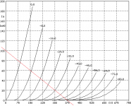
Okay, just by fooling around with the EL34 triode curves from Audiomatica, it looks like you could get about 2.5W output into 3.8K with 225V anode-cathode voltage and idle current at 40mA. Grid bias would be around -18 or -19V. If you use cathode bias, then you want 470R (2W) in the cathode path to ground. Required B+ would be 225V plus bias voltage plus OPT primary loss due to DC resistance. Probably near 260V.
The driver must deliver at least 40Vpp cleanly with voltage gain of 20 (for ~700mV sensitivity), which isn't challenging. Feedback seems mandatory to me, but I assume this is meant to be a learning experience. Turn it every way but loose. If you want 12dB of feedback, for instance, then driver gain must be 12dB (4X) greater, or 80, which is more than single triodes can normally provide. There are many ways to move forward from here.
The driver must deliver at least 40Vpp cleanly with voltage gain of 20 (for ~700mV sensitivity), which isn't challenging. Feedback seems mandatory to me, but I assume this is meant to be a learning experience. Turn it every way but loose. If you want 12dB of feedback, for instance, then driver gain must be 12dB (4X) greater, or 80, which is more than single triodes can normally provide. There are many ways to move forward from here.
Attachments
There are many ways to move forward from here.
Yes is a good starting point. I've read a lot about the single ended amplifiers sound but have never seen one up close. I really want to build one of these.
The work is hard but we learned a lot with this projects.
One possible option on an EI core is to remove the laminations and re-stack them with a gap...
...or go "parafeed".
...or set up something to provide opposite polarity DC flow (does not need to be a tube, could be a Mosfet) (there are a few threads with amps that use this scheme)
_-_-
...or go "parafeed".
...or set up something to provide opposite polarity DC flow (does not need to be a tube, could be a Mosfet) (there are a few threads with amps that use this scheme)
_-_-
I found the magazine article mentioned earlier: "Single Ended Glory for Under $100" by Eric Barbour. It's in Glass Audio volume 7 number 3 (1995) and starts on the title page. There's a semi-scrutable photo of the schematic over here: RE: "Single Ended Glory for Under $100." - mg16 - SET Asylum
Yes is a good starting point. I've read a lot about the single ended amplifiers sound but have never seen one up close. I really want to build one of these.
The work is hard but we learned a lot with this projects.
Then you should build one with a true SE OPT. You want to experience the true sound quality and you will not get that from a PP OPT that is "rigged" to run as a SE tranny. Do it right.
you may be able to get 25% of it's power rating out if the bias current is not to high.
SE transformers saturate at much higher levels, hence their larger size per watt
SE transformers saturate at much higher levels, hence their larger size per watt
Thanks to everyone who helped me in any way.
I decided that I will buy a OT to Single Ended. It's nice to know I have good friends here who like to help me and share knowledge.
Greetings to all.
Remove the laminations would be impossible due to construction of the transformers. They are closed and have a resin. Possibly to avoid vibrations.
I have always used some power transformers as choke (using only the tap of 110v) that way I can some 4.5 H in some small power transformers to improve my power supply filtering. I know this is not the correct because these transformers are built with the laminations (EI) without the gap and that causes loss or overruns etc.. hysteresis..
I took apart one of these yesterday, now I'm going to build again with a gap but still do not know the right material to isolate the I and how many mm gap.
I still have a lot to learn about histereses and saturation of the core, I think these experiment can help me understand this.
Very interesting. I've never seen this scheme.
Yes. I decided that I will buy a OT for Single Endend. Really an adaptation as I imagined it might not show the true value of a Single Ended amp. After insisting, a friend will give me some OT. I'm going to give him a few tubes that have left here.
Thanks for the information. Can be very useful.
I decided that I will buy a OT to Single Ended. It's nice to know I have good friends here who like to help me and share knowledge.
Greetings to all.
One possible option on an EI core is to remove the laminations and re-stack them with a gap...
Remove the laminations would be impossible due to construction of the transformers. They are closed and have a resin. Possibly to avoid vibrations.
I have always used some power transformers as choke (using only the tap of 110v) that way I can some 4.5 H in some small power transformers to improve my power supply filtering. I know this is not the correct because these transformers are built with the laminations (EI) without the gap and that causes loss or overruns etc.. hysteresis..
I took apart one of these yesterday, now I'm going to build again with a gap but still do not know the right material to isolate the I and how many mm gap.
I still have a lot to learn about histereses and saturation of the core, I think these experiment can help me understand this.
I found the magazine article mentioned earlier: "Single Ended Glory for Under $100" by Eric Barbour. It's in Glass Audio volume 7 number 3 (1995) and starts on the title page. There's a semi-scrutable photo of the schematic over here: RE: "Single Ended Glory for Under $100." - mg16 - SET Asylum
Very interesting. I've never seen this scheme.
Then you should build one with a true SE OPT. You want to experience the true sound quality and you will not get that from a PP OPT that is "rigged" to run as a SE tranny. Do it right.
Yes. I decided that I will buy a OT for Single Endend. Really an adaptation as I imagined it might not show the true value of a Single Ended amp. After insisting, a friend will give me some OT. I'm going to give him a few tubes that have left here.
you may be able to get 25% of it's power rating out if the bias current is not to high.
SE transformers saturate at much higher levels, hence their larger size per watt
Thanks for the information. Can be very useful.
The gap distance can be found by measurements.
There are a number of resources online, including the Radiotron Designer's Handbook, that discuss the gap WRT chokes. This is the same in transformers.
You've got a trade-off between the measured inductance (which relates to the LF response limit) and the current before seeing a significant swing in inductance based upon the saturation of the core.
The gap is usually small, as in "paper thin".
It needs to be fairly well controlled in thickness.
Materials used include a variety of insulators, but the key is that they need to be dimensionally stable, and you need to get the right thickness.
Fwiw, nothing wrong with doing a "parafeed" with a PP output transformer...
_-_-
I seem to remember that a few years back, there was someone using old microwave oven transformers, that is the HT winding as a parafeed choke.
An observation I made a few years ago. I have a rebuilt Russian Priboi amp (was 50W PP, became 12W PP) that I brought to friends of mine for a weekend of tubes, fullrangers and music. After listening to my amp for a while I decided to take the lid off and noticed that one OP tube was not glowing, but music still came from both channels w/o distortion. Obviously tje amp work with just push or pull working, and the transformer now working as a SE transformer.
There's also a project on the web with ECL82s and a 100V line transformer.
I wouldn't use a PP tranny in an SE project, apart from the odd matrix amps:
Return of the Darling
There's also a project on the web with ECL82s and a 100V line transformer.
I wouldn't use a PP tranny in an SE project, apart from the odd matrix amps:
Return of the Darling
- Status
- Not open for further replies.
- Home
- Amplifiers
- Tubes / Valves
- Ultra linear OT PP 30W/25W for SE amp of low power? Safe?