
And what is a pentode behaving like?!...Sorry, cascodes are used there.
Different variants.
The cascodes would have a high impedance feedback point (top grid 1) for the R divider to drive, while the pentode screen grid draws non-linear current in most ordinary cases.
With the plate V and screen V related by a fixed ratio however, the screen current should be a fixed fraction of the plate current. So the R divider ratio will be off due to the screen current, but should still maintain a fixed ratio.
I probably was the 1st one to post the pentode scheme 15 years ago, or Jan E Veiset who used the scheme for a local N Fdbk design.
Jan's design, unfortunately the pics are gone now.
https://www.diyaudio.com/forums/tubes-valves/114216-feedback-scheme.html#post1383316
Last edited:
I was using the pentode version of this scheme in an Ultra Linear analysis thread quite some years back, and I was surprised then at how linear the output was ( using a sound card FFT to analyze the results).
Then Jan Veiset came up with his ingenious driver stage screen N feedback thread (the link above) and that was when I realized the constant V ratio between plate and screen was keeping the screen current proportional to the plate current, so making the screen look like a constant resistance. Jan obviously saw that 1st when he came up with his ingenious design.
Unfortunately, Jan's linked amplifier had stability problems, but these likely were due to several other feedback loops. Was a rather complex and ambitious design that needed a very high performance OT to maintain phase integrity.
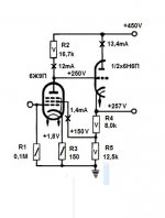
As the tubes warm up, the pentode plate resistor should pull the triode grid upwards until the pentode screen voltage (from triode cathode and R divider) comes up and stabilizes at the operating point. Tricky part is figuring how much current the screen grid will draw and hence affect the R divider. Probably will be some variation across different pentode tubes with varying screen alignment.
Most likely the scheme was considered in some research journal way back when (like 50s?) but got discarded for an unreliable operating point. But it does work well for low distortion, low Z out.
The scheme has also been used to DC stabilize a Concertina splitter driven by a pentode stage. A cap gets added to keep the audio signal out of the servo loop then.
Another extension could be to add a 3rd resister in the divider string, and connect the cathode of the pentode to it. That would stabilize the operating point. Could add a big cap across that bottom 3rd resistor to just work for the DC operating point. Getting complex to calculate out the R values. OOPs! I guess not! Wrong phase to servo control. Never mind this extension.
Last edited:
For stability, the grid current should be less by an order of magnitude of the current of the P-divider
At least Audio Research used transistors so no problem with warming up timing...the difference in conductance is also going to work in favor of the hybrid form...Tektronix used to bootstrap the cathode to g2 with a bipolar transistor in its early hybrid designs...
I think George (Tubelab) may be using something like this for his new "UnSet" drive. Likely with an added Mosfet follower driving the pentode screen grid. Not really necessary though due to the proportional currents keeping the screen resistor-like.
Audio Research used transistors so no problem with warming up timing...
So there was some concern that the pentode would warm up 1st, and hold the plate down, latching the thing (screen) in an off state?
Or, that the triode would warm up 1st and over-voltage the screen grid?
I guess if the screen grid drew too much current, it could hold down the screen V across the R, but then the plate V would go up and the triode would work hard to pull it back up. Well, use a beam tube for low screen current.
The simplest configuration always powered up for me in the past. But then they were $1 tubes and beamers too, so I didn't worry about bad start-ups.
Last edited:
The first question here is why are we using tubes ?Are we doing it because we love more valves or because they have something valuable?In any circuit i tried being it cascode , bootstrap, mu-follower...i always preferred a semiconductor for the upper device.Less fuss with the filament lifting, additional noise, timings, too high impedance, etc...I think that Audio research had some of the most complicated designs that used tons of valves yet they used transistors when better suited. I simply hate using more devices than needed.
A Mosfet makes good sense for the follower or top cascode for sure. No problem with that. But there are some who will scream when they see the schematic. Someone needs to come up with a schematic symbol for a Mosfet that looks like a tube.
Last edited:
The first question here is why are we using tubes ?Are we doing it because we love more valves or because they have something valuable?
Pentode tubes are the only device that can smoothly change transmission properties. From pentode to triode. When the load line will be prependicular to the current-voltage characteristic. Or from another advantageous angle.
The cascodes would have a high impedance feedback point (top grid 1) for the R divider to drive, while the pentode screen grid draws non-linear current in most ordinary cases.
With the plate V and screen V related by a fixed ratio however, the screen current should be a fixed fraction of the plate current. So the R divider ratio will be off due to the screen current, but should still maintain a fixed ratio.
I probably was the 1st one to post the pentode scheme 15 years ago, or Jan E Veiset who used the scheme for a local N Fdbk design.
Jan's design, unfortunately the pics are gone now.
https://www.diyaudio.com/forums/tubes-valves/114216-feedback-scheme.html#post1383316
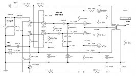
Here is my version of that kind of NFB. But instead of back to screens of a pentode pair I went all the way to a differential cascode pair. The NFB is to the upper grids of the cascode.
I got the idea from a visit to Bill Perkins of PEARL (Perkins Electro Acoustic Research Lab) in Calgary around 1992 during a sales trip there. Bill was using that kind of NFB to pentode screens in a few of his somewhat exotic amps.
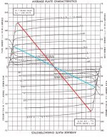
The cct stuck in the back of my mind until retirement. This project had three objectives in mind, PP 6V6s in Class AB2 with a corrected loadline, NFB to a Cascode Pair & how is the transient response effected by a limited PS.
I got going in early 2013. So without digging out the complete test results this thing manages 27 real watts running from a regulated PS, quite a bit less on its own. And looks like the resulting NFB in this case is 7.8 db.🙂
Attachments

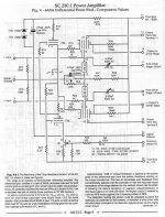
That 2013 date was when I formalized the info on the cascode front end PP Class AB2 amp. It was built & running in 2001 but never got to the point of an article for publication.
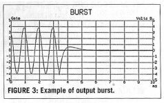
Not long after in 2002 I did a piece on an analogue burst gate.
I couldn't afford a General Radio 1396A. The PP 6V6 amp was used as the test object to get results for the article.
Here is some of the original information used in that piece, finally published in AudioXpress, Nov 2003.
Going thru my notes looks like I didn't measure the Damping Factor (DF), something that needs to be done. The amp is sitting here on the shelf. Watch this thread!!🙂
Attachments
-
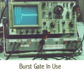 Burst Gate In Use.jpg99.9 KB · Views: 62
 -
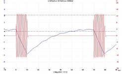
 Burst Example on the Pico Scope.jpg88 KB · Views: 54
 -
 2013_03_23_002.jpg67.8 KB · Views: 123
 -
 6V6GTA 14W 4 PushPull C 7WB.jpg84 KB · Views: 126
 -
 Burst Gate Reference AudioXpress Nov 2003 p33 150 dpi.jpg483.3 KB · Views: 72
 -
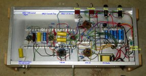 IMG_1383 Cascode Amp Bottom A 14W E Flash Labelled.jpg539.3 KB · Views: 65
 -
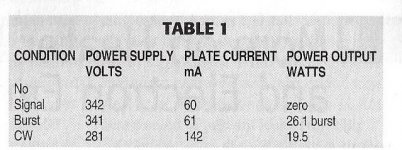 PP 6V6 Cascode Front End Burst Results.jpg82.7 KB · Views: 76
Thanks John for posting the info on the UL and cascode driver amps. Interesting to see this has been around a while. I figured the screen N Fdbk got tried some while back in some industry journal, but never became popular due to the fear of non-linearity from the usual badly behaved screen current.
Jan's design was the first time I saw consideration of proportional screen and plate V's to get screen current proportional to plate current, for linearity purposes.
I did see an amplifier posted a long while back that took the global N Fdbk back to an input pentode screen grid instead of the usual cathode. Guess they wanted some 2nd harmonic.
When I get moved to bigger quarters soon, I'll try testing the tracking screen current on a scope versus plate current to see if it is really linearized/proportional (with proportional Vs).
Next project in the queue however is the "Grunge Meter". Nothing revolutionary in principle, but maybe in practice. A panoramic plot of amplifier gain versus input signal voltage. The SS designers have had this tool for some time, but I never see anything like it in tube literature or practice. Elegant for class AB P-P crossover, but works for anything. Easy to do even.
Wait till we see "Crazy Drive" on the Grunge Meter!.... Flat line gain?....
Last edited:
- Home
- Amplifiers
- Tubes / Valves
- Ultra-linear driver