I always had in thought that Jfets will have better details than tubes but I guess even tubes does it. Erno Borbley states in his article about the Telefunken tubes and jfets and he preferes jfets. I havent yet tried the tube input and would like to test the tube input version. I agree the tone of tube is always better than any solidstate but in my experience I heard alot of tubes 6sn7, 12ax7, 6GD, 300b, KT88, KT150, EL84 but they always somehow use to give over warm sound but the microdetails were not as much as jfets. Whats your call on this? I think even Jwilhelm also stated this on other thread.
You are trying to judge, based on not enough information.
It very much depends on the conditions.
It's like - what engine is better, with carburetor or with injector?
You may think - the one with injector.
But now, if the one with carburetor is a 300hp V8 Hemi, and the one with injector is 80hp 4-cilinder something - which one is better? Again - what is important for you? Performance or fuel economy?
Most of the tube designs, referred to as "warm sounding" are simple common cathode stages with local degeneration and no or low global feedback. This is where you get the warm sound with higher or lower level of even harmonics dominating. When you're saying "I heard alot of tubes 6sn7, 12ax7, 6GD, 300b, KT88, KT150, EL84" - most likely, you have listened them in these conditions.
Hybrid design, like TubSuMo, is incomparably more sophisticated, having high OLG and lots of feedback. The stage, mostly influencing the sound there, is the VAS (carefully designed for highest speed and linearity). Not the input stage. So there's no warm sound there, but there is a highest level on micro-detail and dynamics.
Key advantage of using the tube in the input LTP - excellent fast transients handling. High speed with low noise. Low transconductance tube is used on purpose. Gain of every stage is carefully tuned.
jFETs - great devices, although many of the good old ones are out of production these days. They are also very different. You can't use 2SK170 in the stage, designed for 2SK246. As well as vice versa.
jFETs at the input are very good, assuming all the rest is done properly.
What to use at the input is a question each particular designer answers to himself depending on lots of things. LTP or diamond? Single-sided or complementary? Low gain IPS or high gain IPS? Feedback - current, voltage, nested differential? How much local degeneration required? What happens to phase? Stability? ... i can continue with these questions ...
Lots of other things influence the sonic quality - the way your feedback is arranged, amplification principles and topologies. I like using common base / gate cascades in my recent designs, for example, as well as current coupling / current drive in the cascades.
The main idea is to have as low distortion as possible in each cascade as well as in the whole amplifier open loop. Higher speed, wider bandwidth, less harmonics, lower phase shifts, less inter-stage impedance modulations, etc.
The better your original amplifier is -> the less you have to correct with the feedback and compensation -> the better the sound is. Slightly "simplified" statement, but you get the idea.
In many cases, even excellent designs are spoiled by implementation - I mean, primarily poor PSU build and poor wiring / grounding. This is what influences the sound most of all. As well as unconditional stability, handling any kind of signal, driving any reasonable load.
I agree the call. Jfets do have their merit but can the warmth of the tube ruin the micodetails of the music?
I agree regarding the various stages and topologies but at the same time im talking about key element in the entire design. Tube vs jfet. Now its all about can tube give me the microscopic details if I replace jfet with tube and rest being the same.
I agree regarding the various stages and topologies but at the same time im talking about key element in the entire design. Tube vs jfet. Now its all about can tube give me the microscopic details if I replace jfet with tube and rest being the same.
My hearing isn't a fair judgement for an amplifier. I have hearing damage causing me to hear differently than most other people. I hear low and high frequency better than most, but mid range, especially female vocal range is poor. If anything effects the high frequency details, it's blatantly obvious to me, where others may actually prefer how this sounds.
My TubeSoMo build sounded like it had a low pass filter on it. I'm sure this was due to a build error on my part, not a design flaw or from having a tube input. I had others listen to my build, and they noticed the same immediately. I'm sure others who built it would have said something if theirs was like mine, but everyone else who has built it said it sounded good. I'm building another pair of these to operate with the NS-OPS output boards to compare sound and try to figure out where I went wrong with the first set.
Anthem amplifiers are manufactured not far from me and the stereo shop I deal with regularly was a dealer for them. I've listened to many of their early tube design amplifiers, and really couldn't tell the difference between them and a very good solid state design. I think others must have found the same, as Anthem has since switched to completely solid state designs.
I agree the call. Jfets do have their merit but can the warmth of the tube ruin the micodetails of the music?
I agree regarding the various stages and topologies but at the same time im talking about key element in the entire design. Tube vs jfet. Now its all about can tube give me the microscopic details if I replace jfet with tube and rest being the same.
As I just mentioned, my build of TubSuMo provides enormous amount of micro-detail and dynamics. Evan (member evanc) has built a number of them and I listened to his system as well - he uses TubSuMo particularly for the mid + high frequency bands. Just try it and you'll hear.
I agree. The tubsumo has great detail. I'm not sure why folks think tubes can't do fine detail. Tubes have transmitted and received radio waves for decades. I'm almost ready to test a fetsumo. The last parts should arrive Monday. I'll try to give a comparison between the two.
great Ill try to work on that once and see myself. If I get better tonality with details then yes will go with tubes at input. I feel it would do so.As I just mentioned, my build of TubSuMo provides enormous amount of micro-detail and dynamics. Evan (member evanc) has built a number of them and I listened to his system as well - he uses TubSuMo particularly for the mid + high frequency bands. Just try it and you'll hear.
As I just mentioned, my build of TubSuMo provides enormous amount of micro-detail and dynamics. Evan (member evanc) has built a number of them and I listened to his system as well - he uses TubSuMo particularly for the mid + high frequency bands. Just try it and you'll hear.
So the 21st century protection board is must to run the Tubsumo amplifier?
Can I just trigger the ops after 30secs wouldnt that be sufficient?
In general i use two trafos one for the IPS+VAS and one Large for the OPS alone so what if I use 30sec delay for the OPS?
Yes you can trigger it after 30 seconds but how are you going to do that? If you forget your speakers will be in peril.
So the 21st century protection board is must to run the Tubsumo amplifier?
Can I just trigger the ops after 30secs wouldnt that be sufficient?
In general i use two trafos one for the IPS+VAS and one Large for the OPS alone so what if I use 30sec delay for the OPS?
Yes, you can do it this way. But! Both NFB and servo are taken from the output (that is disconnected during the first 30 seconds according to your plan), so output potential will take some time to zero out after you power on the output stage.
In any case, any amplifier with DC connection to the speaker, must be equipped with DC offset protection. Most of the people, interested in high-quality amplifiers, own expensive, sometimes custom-made, speakers. Probability to fry them, if something goes wrong with an amplifier, must be close to zero. That's why 21-st century board connects the speakers only if output DC and output stage over-current conditions are ok, and disconnects them immediately, if they become not ok. DC offset protection is a must!
so using just a DC detection and protection system is fine I believe. Do we really need advanced Micro controller based protection system for the Tubsumo?Yes, you can do it this way. But! Both NFB and servo are taken from the output (that is disconnected during the first 30 seconds according to your plan), so output potential will take some time to zero out after you power on the output stage.
In any case, any amplifier with DC connection to the speaker, must be equipped with DC offset protection. Most of the people, interested in high-quality amplifiers, own expensive, sometimes custom-made, speakers. Probability to fry them, if something goes wrong with an amplifier, must be close to zero. That's why 21-st century board connects the speakers only if output DC and output stage over-current conditions are ok, and disconnects them immediately, if they become not ok. DC offset protection is a must!
In the other thread CFA VFA Rumble Ostipper speaks about the super pair stability is very hard but few pros of having soft clipping behavior at the higher output levels from the super pair is some what considerable.
You can use whatever you like with it, but the simplest solution was the microcontroller based protection design. It takes care of delaying the actual amp start up until the tubes are warmed up first, and then takes care of DC offset detection, output stage overcurrent detection, heat sink temperature monitoring, soft starting, and mains power loss detection in a single system, and any timing feature can be fine tuned in seconds via software.
This is a whole lot more complicated to do with discrete analog circuits, is a lot more work to fine tune, and doesn't actually work as well because the microcontroller system ties all these circuits together and makes them compliment each other in operation
This is a whole lot more complicated to do with discrete analog circuits, is a lot more work to fine tune, and doesn't actually work as well because the microcontroller system ties all these circuits together and makes them compliment each other in operation
so using just a DC detection and protection system is fine I believe. Do we really need advanced Micro controller based protection system for the Tubsumo?
No, of course, sophisticated micro-controller based control board is not a mandatory requirement here.
However, simple DC offset protection board is just a minimum, required for protecting the speakers. A cheap board utilizes a cheap mechanical relay for disconnecting the speakers, having the following two disadvantages:
1) possibly influencing the sound, as inexpensive contact groups may perform poorly under tge high load currents;
2) trying to disconnect the speaker, in high-power conditions - for example, one of the output transistors has shorted and you have the rail connected to your speaker - a cheap relay may also fail to disconnect, killing the woofer (plasma arch will "glue" the contact group). I'm aware of such incidents.
It all depends on the level of reliability, convenience and safety you'd like to have.
Sophisticated board will monitor not only DC offset, but also over-current and over-temperature conditions, shutting down the system before DC offset will even appear at the output (reliability). Our control board also provides indication of the reason for shutting it down (convenience). We are also using the MOSFET-based solid-state relays at speaker connection, as well as controlled rails option, disconnecting the rails in case of emergency, providing additional reliability and saving the amplifier components (safety).
I like to give examples with the cars 😉
Some simple inexpensive 10-years old car is enough for driving around in the city.
But some people buy Maserati. Many times more expensive. But far superior in terms of reliability, convenience and safety.
Feel free to choose what you choose to choose 😛
I too was reluctant to build the microprocessor controlled amp controllers. Once I did it I realized that it was easy. vzaichenko and jwilhelm have done all of the hard work. All we need to do is follow directions and solder some parts. The system works well and can be used in future projects if required.
Regarding the non switching OPS I see a old hitachi circuit which is capable of non switching OPS the specs of Hitachi HMA 7500MKII is very impressive very similar to valery output.
https://www.usahifi.com/sites/defau...manuals/Hitachi HMA-7500MKII Amp Brochure.pdf
https://www.usahifi.com/sites/defau...manuals/Hitachi HMA-7500MKII Amp Brochure.pdf
Attachments
Regarding the non switching OPS I see a old hitachi circuit which is capable of non switching OPS the specs of Hitachi HMA 7500MKII is very impressive very similar to valery output.
https://www.usahifi.com/sites/defau...manuals/Hitachi HMA-7500MKII Amp Brochure.pdf
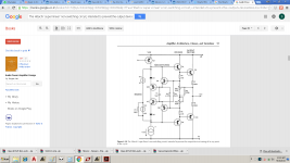
This one is also a non-switching one, but different way of setting the clipping reference.
This one is also a non-switching one, but different way of setting the clipping reference.
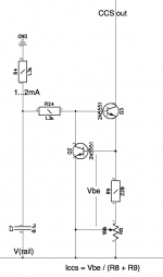
how do we make 4ma CCS? any circuit for it as I see most of the cases for 2ma CCS.
how do we make 4ma CCS? any circuit for it as I see most of the cases for 2ma CCS.
Hi Sandeep,
It's as many mA, as the designer wants it to be.
There may be many topology options - this is just one of them. See attached.
You set CCS current with (R8 + R9) value.
R8 is a trimmer, so you can set the desired current precisely.
Vbe = 0.65V (roughly).
Values of R4, R24 depend on the rail voltage.
(R4 + R24) = (V(rail) - Vbe * 2) / 2mA
Cheers,
Valery
Attachments
I think there are few LED versions for Vref to base. Do you know anything like that?Hi Sandeep,
It's as many mA, as the designer wants it to be.
There may be many topology options - this is just one of them. See attached.
You set CCS current with (R8 + R9) value.
R8 is a trimmer, so you can set the desired current precisely.
Vbe = 0.65V (roughly).
Values of R4, R24 depend on the rail voltage.
(R4 + R24) = (V(rail) - Vbe * 2) / 2mA
Cheers,
Valery
- Home
- Amplifiers
- Solid State
- Ultra-high performance, yet rather simple - hybrid and more!