Thimios will test. 🙂🙂
OS
Good plan. Don't have me test it. You know where that will lead. 🙁
Guys, I'm back again.
Yes, what is really strange - I've just got two channels working here with no sign of oscillation... this makes troubleshooting more difficult.
Terry, can you please try a few of things:
- first, let's try to connect the right sipe of the additional caps right to the PD+ and ND-;
- if the above doesn't help, let's increase C23, C24 to 22p;
- if the above doesn't help, let's remove R36, R37.
There are more heavier options, like adding caps between collectors of Q4, Q6 and Q5, Q7, increasing C18, increasing C9...
But let's start with those three above first.
Cheers,
Valery
Attachments
Valery
Perhaps the reason for some of the problems is that complicated compensation can make it difficult to estimate the stability correctly.
For instance, a simple probe in the outer loop is not accurate.
A four section amp, like yours, adds even more possibilities.
How does your simulator handle Return Ratio calculations?
And where in the circuit have you checked?
Best wishes
David
For instance, a simple probe in the outer loop is not accurate.
 A hard truth ! (frustrating ,as well).
OS
Good plan. Don't have me test it. You know where that will lead. 🙁
I have the utmost confidence in your tests as well. 🙂
OS
Hi Valery,
I will try your suggestions in the morning. Thanks for staying with this. Do you have any ideas why your amp works as is and mine doesn't? Can't wait to try this.
I almost ordered more boards today but it looks like there will be some changes so hopefully I can get it working this weekend and then you can add the pads and traces to accommodate the new devices.
Thanks, Terry
Valery
Perhaps the reason for some of the problems is that complicated compensation can make it difficult to estimate the stability correctly.
For instance, a simple probe in the outer loop is not accurate.
A four section amp, like yours, adds even more possibilities.
How does your simulator handle Return Ratio calculations?
And where in the circuit have you checked?
Best wishes
David
Hi David,
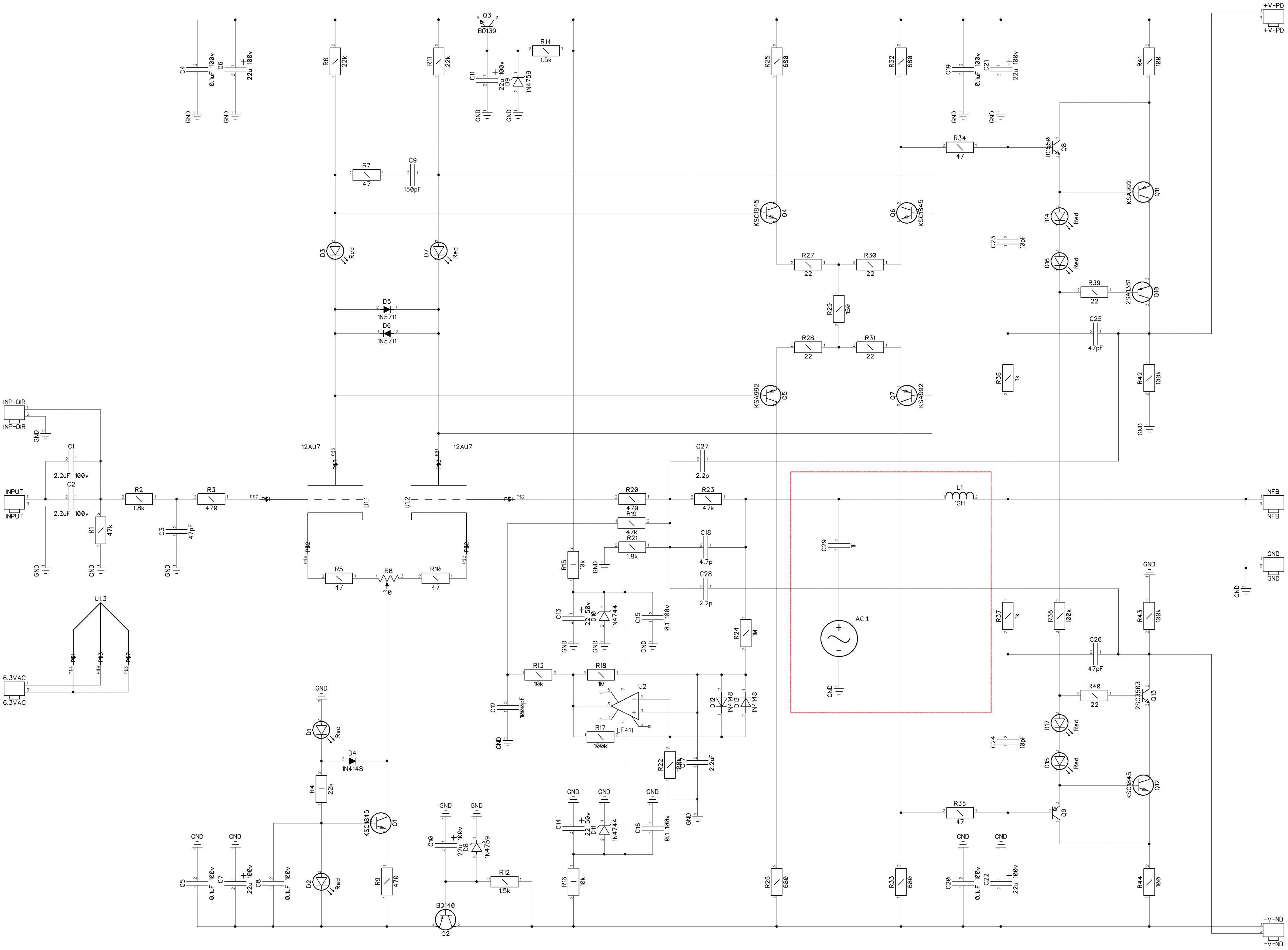
Most often I use the method, described by Bob Cordell (huge inductance + huge capacitance + voltage source -> AC analysis) - see attached.
In many cases it gives rather good results. When I can, I compare with LTSpice curves and margin values, published by others, and it's very close.
I agree, in complicated cases it may be not so accurate.
What is still rather strange - I'm torturing my prototype here and cannot make it oscillating. What is the difference?
Cheers,
Valery
Attachments
Hi Valery,
I will try your suggestions in the morning. Thanks for staying with this. Do you have any ideas why your amp works as is and mine doesn't? Can't wait to try this.
I almost ordered more boards today but it looks like there will be some changes so hopefully I can get it working this weekend and then you can add the pads and traces to accommodate the new devices.
Thanks, Terry
Yes, let's clear this one out before ordering. I continue testing, trying to reach oscillation here...
Maybe the tubes are the difference? Still hard to believe they influence stability that much.
BTW, sometimes I get a tube, having the triodes very different within the tube. Even servo cannot balance it out.
Out of 4 tubes - 3 are perfectly balanced, 1 is completely "out of range".
BTW, sometimes I get a tube, having the triodes very different within the tube. Even servo cannot balance it out.
Out of 4 tubes - 3 are perfectly balanced, 1 is completely "out of range".
So weird, Mine won't work at all with the Slewmaster OPS. D15 an D17 barely light and pulse and that is without a load. With a load you can actually hear sizzling. Looking forward to trying the new ideas. I love it when we work through issues and end up with a great playing amp.
Blessings, Terry
Blessings, Terry
...Most often I use the method, described by Bob Cordell ... - see attached.
Unfortunately you have it placed incorrectly, even to probe the TMC loop.
And since you have a 4 section amp there is more to do.
When I can, I compare with LTSpice curves ...published by others, and it's very close.
The LTspice simulator itself is very accurate, but many other people make the same mistakes, and then think it's correct because it matches.
The best example of this is the absurdly low value of distortion many people claim for MOSFET amplifiers, because they use the same worthless models.
... in complicated cases it may be not so accurate.
Your amp is probably one of those complicated cases, it would be nice to check.
... cannot make it oscillat[e] What is the difference?
More than just stability analysis differences, I assume.
But if we did a correct stability analysis we could learn more and perhaps see where the critical components are.
Could you put the circuit into an ASC that I can read with LTSpice?
I have built some LTSpice test modules and I can look inside.
Best wishes
David
LTSpice
Hi David,
Here is what I've managed to come up with - based on Bimo's model he did for jfet option, Joel Tunnah'd tube models file is also here. I'm really struggling with custom (well, not embedded) components in LTSpice - sorry 🙄
It's got the slewmaster OPS attached here - that's fine.
Your help will be greatly appreciated.
Cheers,
Valery
Unfortunately you have it placed incorrectly, even to probe the TMC loop.
And since you have a 4 section amp there is more to do.
The LTspice simulator itself is very accurate, but many other people make the same mistakes, and then think it's correct because it matches.
The best example of this is the absurdly low value of distortion many people claim for MOSFET amplifiers, because they use the same worthless models.
Your amp is probably one of those complicated cases, it would be nice to check.
More than just stability analysis differences, I assume.
But if we did a correct stability analysis we could learn more and perhaps see where the critical components are.
Could you put the circuit into an ASC that I can read with LTSpice?
I have built some LTSpice test modules and I can look inside.
Best wishes
David
Hi David,
Here is what I've managed to come up with - based on Bimo's model he did for jfet option, Joel Tunnah'd tube models file is also here. I'm really struggling with custom (well, not embedded) components in LTSpice - sorry 🙄
It's got the slewmaster OPS attached here - that's fine.
Your help will be greatly appreciated.
Cheers,
Valery
Attachments
Guys, I'm back again.
Yes, what is really strange - I've just got two channels working here with no sign of oscillation... this makes troubleshooting more difficult.
Terry, can you please try a few of things:
- first, let's try to connect the right sipe of the additional caps right to the PD+ and ND-;
- if the above doesn't help, let's increase C23, C24 to 22p;
- if the above doesn't help, let's remove R36, R37.
There are more heavier options, like adding caps between collectors of Q4, Q6 and Q5, Q7, increasing C18, increasing C9...
But let's start with those three above first.
Cheers,
Valery
Hi Valery,
OK, starting at the top;
Relocating the 2p caps made things worse so I disconnected them.
I tried adding 10p to C23 and C24. Very slight improvement. Tried adding 15p, about the same, still bad oscillation.
Removed R36 and R37, BINGO!!!!! "NO OSCILLATION"
I haven't tried it with the Slewmaster OPS yet but with the lateral OPS it is beautiful. May I assume we are good or is the circuit now crippled and needs further adjustment?
Thanks, Terry
Spoke too soon. After the success I actually played music through it and it sounded great. Couldn't see any fuzz on the scope. So then I pulled R36 and R37 on the other board and hooked it up. Awk, oscillation. So I add the 15p to C23 and C24 like I have on the working board. No change. I hook the working board back up, and the oscillation is back on that board now. I have 4 tubes laying here. They all worked a half an hour ago in the good board. I tried all of them with the same results. This is crazy. Next I'm going to try replacing all of the connecting wires and see if that makes any difference. There has to be something I'm not seeing.
Sounds to me like you're lacking current in the signal to the VA stage.
How much current should I have and where do I measure for that?
Here is the latest in the saga. I decided I would try hooking up a 5pf cap with some probes so I could stab around the circuit and see if I could improve things. So I clipped one end to the junction of R20/R23. Instantly the oscillation was gone. No other action at this point, I simply attached one end of the probes to that junction. I then began touching the other end around the circuit to see if I could find a spot to attach the other end of the cap. Every place I tried caused a slight increase in oscillation. The best result was to simply have that test probe just hang off into the air. This worked on both boards.
So, where do I go from here?
Thanks, Terry
Hi Valery,
OK, starting at the top;
Relocating the 2p caps made things worse so I disconnected them.
I tried adding 10p to C23 and C24. Very slight improvement. Tried adding 15p, about the same, still bad oscillation.
Removed R36 and R37, BINGO!!!!! "NO OSCILLATION"
I haven't tried it with the Slewmaster OPS yet but with the lateral OPS it is beautiful. May I assume we are good or is the circuit now crippled and needs further adjustment?
Thanks, Terry
So it didn't like TMC in your case. Now, with simple miller it feels better.
I'm researching the behavior more deeply, maybe with David help we will get more precise understanding of the loop gain curves.
Measurements to check:
- voltage across R32 = 960mV;
- voltage across R41 = 940mV;
Giving us 1.4mA through second LTP and 8mA VAS current.
Here is the latest in the saga. I decided I would try hooking up a 5pf cap with some probes so I could stab around the circuit and see if I could improve things. So I clipped one end to the junction of R20/R23. Instantly the oscillation was gone. No other action at this point, I simply attached one end of the probes to that junction. I then began touching the other end around the circuit to see if I could find a spot to attach the other end of the cap. Every place I tried caused a slight increase in oscillation. The best result was to simply have that test probe just hang off into the air. This worked on both boards.
Terry,
Can you post the schematic version (or a link to it) that you are working from? I'm not seeing a junction at R20 and R23 like you describe. I'm probably looking at an old version.
- Home
- Amplifiers
- Solid State
- Ultra-high performance, yet rather simple - hybrid and more!