Good point. I always use socket - good one, with gold-plated pins.
I did the same. The sockets were 4 times the cost of the ic. I think I'll start using them again, then solder the ic into it when done. I hate desoldering ics.
Just use a known good servo'ed amp to test the whole strip of IC's.
Blew one TL by not grounding the IPS 😱 - glad it's socketed.
PS - tested all my TL072's on one of my socketed spooky amps. All servo'ed
to <.1mV - all are good.
I have the meg ohm servo sense and a cheap socket - still low mV ... no issue.
OS
Blew one TL by not grounding the IPS 😱 - glad it's socketed.
PS - tested all my TL072's on one of my socketed spooky amps. All servo'ed
to <.1mV - all are good.
I have the meg ohm servo sense and a cheap socket - still low mV ... no issue.
OS
I think sockets are more of a problem after time. The cheaper spring tin ones develop resistance over years. Freshly plugged in will be good for a while because of the wiping action. I've got an electronics nazi buddy that always swore by the round pin gold ones that slightly deform the ic pins. I've gotten used to using them.
I suppose you right about that. I'm afraid I am guilty of not being too concerned about long term since I have so many amps now most of the new ones will never see every day use. I figured since the servo doesn't see much voltage or current, there was not much strain on the pins. Maybe I'm wrong.
In order to make my building experience more enjoyable, I began stockpiling parts. Buying resistors in every value, extra caps with each order and many Onsemi outputs through their samples program. These sockets seem to work just fine and I can but 100 at time for chump change. It just makes my style of building, quicker and easier.
Blessings, Terry
Terry you and I are almost the complete opposite. Don't get me wrong I love to build stuff but my time is so limited that I usually think long and hard about how to use my me time.
As far as listening goes we have a small home..there can be only one real system. That system comes on most afternoons and plays right up till bed time. I enjoy stuff that can be turned on and play background for the family and satisfy me when I want to sit in the "sweet spot" and enjoy.
Evan
As far as listening goes we have a small home..there can be only one real system. That system comes on most afternoons and plays right up till bed time. I enjoy stuff that can be turned on and play background for the family and satisfy me when I want to sit in the "sweet spot" and enjoy.
Evan
Hey Evan,
I don't have a large home either but I do have my own room to work in and that is where my JBLs are set up. The rest of the house belongs to the wife so we have a surround system there that is all Yamaha. No DIY allowed. All "critical listening" is done in "my room". 😀
I'm retired now so time is not really a problem. My biggest problem is the ever growing pile of amplifiers I'm acquiring. I'll have to find an outlet for those some day.
Blessings, Terry
Working on it. I am switching my 5 pair slewmonsters to the chassis with the +-85volt power supplies and putting your amps into chassis with +-72 volt supplies. Should be done today.
A question for the future. I believe I could fit two of your output boards on one heatsink. would a balanced setup be doable?
Evan
A question for the future. I believe I could fit two of your output boards on one heatsink. would a balanced setup be doable?
Evan
Balanced setup would be a cool option - front-end topology is very suitable for it. I need to check couple of things with regards to DC servo in this case - will do.
BTW, I have looked at K1058/J162 SOA - Terry is right, +/-85V would be too much for them. So you are doing the right thing.
Cheers,
Valery
BTW, I have looked at K1058/J162 SOA - Terry is right, +/-85V would be too much for them. So you are doing the right thing.
Cheers,
Valery
OK...finally a listening report. I cased up both channels. The power supply is +-74vdc. The bias maxes out at just less then 100ma per pair. I may try a 100ohm pot to try to get a bit more bias. DC offset bounces around 1mv. After about an hour at moderate volume the heatsinks are about 30c the outputs are about 36c.
Sounds VERY nice. Where the bjt output slewmonster sounded a bit clinical (my wife called it crispy) this amp is a bit more relaxed. This isn't a bad thing at all....All the detail is there but the midbass feels a bit more filled in. At the highest volume the 5 pair slewmonster has the edge. This unit will stay in the system for the time being.
To Valery and all the others who are helping me along a great Thank You.
Evan
OK...finally a listening report. I cased up both channels. The power supply is +-74vdc. The bias maxes out at just less then 100ma per pair. I may try a 100ohm pot to try to get a bit more bias. DC offset bounces around 1mv. After about an hour at moderate volume the heatsinks are about 30c the outputs are about 36c.
Sounds VERY nice. Where the bjt output slewmonster sounded a bit clinical (my wife called it crispy) this amp is a bit more relaxed. This isn't a bad thing at all....All the detail is there but the midbass feels a bit more filled in. At the highest volume the 5 pair slewmonster has the edge. This unit will stay in the system for the time being.
To Valery and all the others who are helping me along a great Thank You.
Evan
Now you've got me really wanting to get mine bebugged!😀
Definitely worth the time. When I have trouble getting something to work it eats at me......I know the answer is there and it bothers me that I can't find it.
Evan, thank you for all the great work you've done and congratulations with the great result achieved 
This one of my favorites as well. 100mA per pair is more than enough in fact - I run my amp at around 80mA per pair. My impression is pretty much in line with yours - the sound is "elastic" in a good way, with lots of micro-dynamic details and solid, low-distortion "velvet" bass (well, PSU high-current capability is important for the last one).
Jeff, I'm also very interested in your impressions, so - you have to make it up running 😉
Evan, thank you for all the great work you've done and congratulations with the great result achieved
This one of my favorites as well. 100mA per pair is more than enough in fact - I run my amp at around 80mA per pair. My impression is pretty much in line with yours - the sound is "elastic" in a good way, with lots of micro-dynamic details and solid, low-distortion "velvet" bass (well, PSU high-current capability is important for the last one).
Jeff, I'm also very interested in your impressions, so - you have to make it up running 😉
I'm waiting on another batch of latfets. I'm going to dig into this DC offset drift issue tomorrow.
Definitely worth the time. When I have trouble getting something to work it eats at me......I know the answer is there and it bothers me that I can't find it.
I know the feeling. I usually wake up around 2 am and start thinking stupid issues. Quite often that's when I figure out what's actually wrong.
This amplifier is what sir?That's right, gate-drain is the right position. I have changed it in the updated board layout, but initial one has it in a wrong way. So, better just put the caps right on transistor pins (side ones).
Sorry for confusion 🙄

This amplifier is what sir?
Hi, on the picture is the output section of TubSuMo amplifier.
You can find the final schematic here:
>TubSuMo OPS as built<
Hybrid front-end of this amp is shown here:
>TubSuMo Front-End<
And here you can see the picture and measurement results of the whole amp (both modules together):
>TubSuMo IPS + OPS<
Cheers,
Valery
Balanced setup would be a cool option - front-end topology is very suitable for it. I need to check couple of things with regards to DC servo in this case - will do.
BTW, I have looked at K1058/J162 SOA - Terry is right, +/-85V would be too much for them. So you are doing the right thing.
Cheers,
Valery
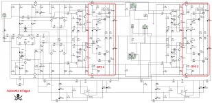
Evan - tried the bridged setup. Double VAS, double servo, double OPS, two NFB loops - works fine in simulation. Also, fully balanced operation is possible (balanced input is easy to arrange).
Output power is limited by OPS modules in this case. With two standard ones I would not go above 250W. However, adding two extra pairs to each side of the bridge (and increasing the VAS current a bit) will allow driving up to some 500W at 8 ohm load with the same rail voltages.
Ultra-high performance super-power 😛
Wanna try? This is a hell of a project. I would build two mono-blocks, each with its own PSU. Balanced inputs. Sort of no-compromise hi-end

In fact, for home use, two standard OPS modules per channel are more than enough...
Bridged IPS requires certain PCB enhancement - not really difficult, having the original in hand.
Overall schematic as simulated is attached - just to give you an idea of the design.
Cheers,
Valery
Attachments
Evan - tried the bridged setup. Double VAS, double servo, double OPS, two NFB loops - works fine in simulation. Also, fully balanced operation is possible (balanced input is easy to arrange).
Output power is limited by OPS modules in this case. With two standard ones I would not go above 250W. However, adding two extra pairs to each side of the bridge (and increasing the VAS current a bit) will allow driving up to some 500W at 8 ohm load with the same rail voltages.
Ultra-high performance super-power 😛
Wanna try? This is a hell of a project. I would build two mono-blocks, each with its own PSU. Balanced inputs. Sort of no-compromise hi-end
In fact, for home use, two standard OPS modules per channel are more than enough...
Bridged IPS requires certain PCB enhancement - not really difficult, having the original in hand.
Overall schematic as simulated is attached - just to give you an idea of the design.
Cheers,
Valery
What is the power output of a single OPS module?
- Home
- Amplifiers
- Solid State
- Ultra-high performance, yet rather simple - hybrid and more!