Ultimate Twin TDA1541a Non-oversampling DAC with tube buffer & reclock set...........
Hi Julien_M,
sorry for my mistake.
I received your email already. pls run in the DAC first.
I will collect all the missing parts & post all together to U.
Bu mainly was the <1.25ppm TCXO. It need some time arrived my hand.
I will follow two used 6DJ8 tubes ( free) to U to compensate my mistake.
thx
thomas
Hi Thomas.
Thanks for your reply and the tubes.
I installed the tube buffer this morning. It sounds really good!!
I haven't done any mods yet. I want the circuit to be well burned in. I only have 2 types of signal tubes for this board: JJ ECC88 and Russian 6n1p. The JJ's were a bit hard, they probably need some more break-in since they haven't been played in a while. Now the 6n1p's sound very smooth and dynamic, this is a really good tube. I've been listening to it all afternoon...
Any comments on how the 6c45pi sounds compared to the 6dj8 types? Is the 6c45pi quieter? I find the 6dj8 circuit a bit noisy. Any improvements in that department?
Regarding the 6c45pi mod using a LT317 and 75R. Should the paralleled 33K resistor (R16, R22, R49, R50) be removed?
I'm planning in getting rid of the inductor, and filtering caps at the input. I'm also thinking about removing the bypass electrolytic caps. I'll probably loose some gain, but transparency should be improved. But I'll wait a bit before starting working on it again, for now I just want to enjoy...
J.
Member
Joined 2002
Julien_M said:Hi Thomas.
I installed the tube buffer this morning. It sounds really good!!
I haven't done any mods yet. I want the circuit to be well burned in. I only have 2 types of signal tubes for this board: JJ ECC88 and Russian 6n1p. The JJ's were a bit hard, they probably need some more break-in since they haven't been played in a while. Now the 6n1p's sound very smooth and dynamic, this is a really good tube. I've been listening to it all afternoon...
Any comments on how the 6c45pi sounds compared to the 6dj8 types? Is the 6c45pi quieter? I find the 6dj8 circuit a bit noisy. Any improvements in that department?
Regarding the 6c45pi mod using a LT317 and 75R. Should the paralleled 33K resistor (R16, R22, R49, R50) be removed?
I'm planning in getting rid of the inductor, and filtering caps at the input. I'm also thinking about removing the bypass electrolytic caps. I'll probably loose some gain, but transparency should be improved. But I'll wait a bit before starting working on it again, for now I just want to enjoy...
Nice case where did you get it ?
jleaman said:
Nice case where did you get it ?
Thanks.
That's Thomas case. I ordered it with the kit.
Member
Joined 2002
I recommend all you guys to remove the onboard connecting terminal and solder the signal wire directly to the board. This made a huge difference in the sound for me.
Member
Joined 2002
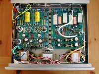
quantran said:I recommend all you guys to remove the onboard connecting terminal and solder the signal wire directly to the board. This made a huge difference in the sound for me.
Right when i get a case ill do this for sure.. But for now ihave to stick to them for when i move it..
as it all sits right now.. velleman pre-amp just there for testing pourpose.
Attachments

quantran said:I recommend all you guys to remove the onboard connecting terminal and solder the signal wire directly to the board. This made a huge difference in the sound for me.
Thanks for the tip Quan Tran.
I agree with you, but for now, I'll leave the terminals on since I'll be tweaking the board. Once I'm done (if there is such a thing), I'll solder everything...
I think the tube noise I'm getting might be related to the AC line. The left channel (the closest to the AC in) has louder noise then the right one. I'll try to shield the power lines. I think removing the bypass capacitors and reducing the gain might lower noise also. I have to try that...
Thanks Quan Tran.
I finished building both re-clock boards, so I'm getting a little inpatient to try them on. But finding a XO of 11.2896 is impossible. I might try Guido Tent XO at a latter time, but for now, I have to wait for my TCXO form Thomas...
I did a few modification in the tube buffer. The voltages were very high, My B+ was at 275VDC! I managed to lower it to 250VDC (still high...). And the filament voltage for the regulator was almost 8VAC! Now it's 6.5VAC.
I also removed the inductor and the first 1n cap off the input. And the cathode bypass caps are gone... All that improved transparency significantly. And reducing the gain significantly lowered the noise issues I was having, almost to non existence. And the sound is now less tubey and more neutral.
I can't wait to try the re-clock boards...
The lower gain is mainly due to the removal of the cathod bypass cap. But the sound is much cleaner without this cap. I was also thinking about the high B+. However the space is too small to put in large resistors.
Your analog stage should be very good already. I believe the reclock module will then be very effective in removing the remaining digital distortion. Before I try the reclock I did not think that jitter has such a large effect on the sound of DAC. However I guess that the reclock is more effective if you use a cheaper transport as I do. If you use CDPRO2 then the difference would not be so large because the digital output from CDPRO2 is good already. You may try I2S connection from CDPRO2 to the DAC as some people do.
Your analog stage should be very good already. I believe the reclock module will then be very effective in removing the remaining digital distortion. Before I try the reclock I did not think that jitter has such a large effect on the sound of DAC. However I guess that the reclock is more effective if you use a cheaper transport as I do. If you use CDPRO2 then the difference would not be so large because the digital output from CDPRO2 is good already. You may try I2S connection from CDPRO2 to the DAC as some people do.
Ultimate Twin TDA1541a Non-oversampling DAC with tube buffer & reclock set...........
Hi Julien_M,
not need to worry about the voltage. after loading will same to 6.3V.
Can U solve the little bit of noise now??
If U use high efficieny speaker I suggest use choe on the HV area & try the CCS on both channel of the Tube Buffer Board.
Parts I supply to u contain two 317 was for Later U diy the CCS use.
Hi quantran,
I was testing for my japanese friend's circuit that use
Jitter reduction with Asynchronous Sample Rate Converter,
For example if we use only CD as the digital source, a very low jitter or call jitter free data steam will be provide.( same 16 bit data)pass from this chip than into the 1541a.
Any comment for this????
This will a little bit same as the reclock but very simple. One chip & one TCXO only.
thx
thomas
Hi Thomas,
Thanks for your reply.
I'll try the CCS on the tube board. But from what I understand from your schematics, it only applies to the 6C45Pi tubes. Do you remove R16, R22, R49 and R50 and replace witht the CCS, or do you add the CCS to it? I've only used 6922/6DJ8 (6N1P) type tubes so far. Could the CCS circuit be applied to 6922/6DJ8 tubes? I'm not quite sure how this circuit is implemented to the tube buffer.
The high filament voltage was the AC for the rectifier tube only, not for the signal tubes.
The reading I had was 7.8VAC with a 0.6A load (the tube was on). I used two 1R25 resistors (one per lead) and I now get 6.5VAC. The AC power in my house is 120VAC and not 110VAC.
For the B+ I replaced R4 and R29 with 15K resistors and I get 252VDC, but 20K will give me a B+ closer to 210VDC.
Anyway this DAC sounds very good otherwise.
Any luck with the TCXO's? I can't wait to try the re-clock circuits. The boards are ready just waiting for the oscillator...
Ultimate Twin TDA1541a Non-oversampling DAC with tube buffer & reclock set...........
dear Julien_M,
not need to worry about the voltage. If the in your home is 120. pls try to adj the resisters to maintain loading oltage of the tube in 6.3~6.4 is OK.
The 1.25ppm TCXO will arrive my hand this month end. I will immediately post to U. BTW, will U care to assistance me to test the new reclock as the jitter free that use the AD1890.
This will be the project for the coming DAC.
http://www.analog.com/UploadedFiles/Data_Sheets/6417611641890_91_0.pdf
thx
thomas
Re: Ultimate Twin TDA1541a Non-oversampling DAC with tube buffer & reclock set...........
Hi Thomas.
Thanks for your reply.
Yes, I'd be glad to help develop your next DAC.
Just let me know how.
Regards,
tube-lover said:dear Julien_M,
not need to worry about the voltage. If the in your home is 120. pls try to adj the resisters to maintain loading oltage of the tube in 6.3~6.4 is OK.
The 1.25ppm TCXO will arrive my hand this month end. I will immediately post to U. BTW, will U care to assistance me to test the new reclock as the jitter free that use the AD1890.
This will be the project for the coming DAC.
http://www.analog.com/UploadedFiles/Data_Sheets/6417611641890_91_0.pdf
thx
thomas
Hi Thomas.
Thanks for your reply.
Yes, I'd be glad to help develop your next DAC.
Just let me know how.
Regards,
Re: Ultimate Twin TDA1541a Non-oversampling DAC with tube buffer & reclock set...........
Hi Thomas
I have no experience with ASRC. However I read the data sheet of the AD1890 chip. It looks like a lot of DSP involved. So it will no longer be NOS DAC? I am not really sure if the complicated processing inside the ASRC could cause any degrade in the digital signal?
The following is taken from AD1890 datasheet
"the AD1890 THD+N specification of –106 dB (at
1 kHz) will rise to –103 dB if the signal makes two passes
through an ASRC. The overall system THD+N specification
will rise to –100 dB with four passes, and so on."
tube-lover said:
Hi quantran,
I was testing for my japanese friend's circuit that use
Jitter reduction with Asynchronous Sample Rate Converter,
For example if we use only CD as the digital source, a very low jitter or call jitter free data steam will be provide.( same 16 bit data)pass from this chip than into the 1541a.
Any comment for this????
This will a little bit same as the reclock but very simple. One chip & one TCXO only.
thx
thomas
Ultimate Twin TDA1541a Non-oversampling DAC with tube buffer & reclock set...........
hi quantran,
yes, if I added ad1890 this wil not be the NOS DAC. But we can use a jumper to set the operation condition. Looks added ad1890 will lowwer jitter than use standard re-clock. any comment for this. new version is AD1895. As I said. I got this chips in god price with the taiwan 2002 version selected 1541a chips. more SMD I an maintain in good price for Diyers.
any comment for this.
thx
thomas
Re: Ultimate Twin TDA1541a Non-oversampling DAC with tube buffer & reclock set...........
Thomas
It would be interesting to try ASRC. Audiophiles usually complain that CDs' sound is not as good as analog sources. I think the main reason is jitter. Lower jitter will result in more analog sound.
Good luck
Thomas
It would be interesting to try ASRC. Audiophiles usually complain that CDs' sound is not as good as analog sources. I think the main reason is jitter. Lower jitter will result in more analog sound.
Good luck
tube-lover said:hi quantran,
yes, if I added ad1890 this wil not be the NOS DAC. But we can use a jumper to set the operation condition. Looks added ad1890 will lowwer jitter than use standard re-clock. any comment for this. new version is AD1895. As I said. I got this chips in god price with the taiwan 2002 version selected 1541a chips. more SMD I an maintain in good price for Diyers.
any comment for this.
thx
thomas
I've done some tweaking and parts swap. I used Panasonic FM and Nichicon HE caps on the DAC power supply, these are very low impedance caps and tend to sound very transparent. I also removed the switch at the S/PDIF input. I just connect and disconnect cables as needed. All connections are 75ohm BNC.
On the tube board, I lower the B+ to 235VDC using 20K resistors (R4 and R29). I used 3W but 2W should be plenty as there's less than 1W dissipation. I also added 100nF bypass polypropylene caps across two of the PS caps (C3 and C43).
I've followed Quan Tran suggestion and solder all my signal connections to the boards.
So far so good. The sound appears a bit smoother than before but I still have to let the caps, resistors, and solder joints break-in a bit.
I'll be trying battery bias tomorrow.
Attachments
- Status
- Not open for further replies.
- Home
- Vendor's Bazaar
- Ultimate Twin TDA1541a Non-oversampling DAC with tube buffer & reclock set.......