Hi Mike,
When using the tube board you must keep the I/V resistors to this is a totally different situation.
I just made the small modification on the opamp board (3K3 -> 680R) and now it plays fine without any distortion 🙂
Regards,
Ronald
When using the tube board you must keep the I/V resistors to this is a totally different situation.
I just made the small modification on the opamp board (3K3 -> 680R) and now it plays fine without any distortion 🙂
Regards,
Ronald
The feedback resistors in my opamp i/v circuit was 1K. That's why 🙂
Yes, 3K3 is way too high even for 1 tda1541a.
Yes, 3K3 is way too high even for 1 tda1541a.
Thank you for the feedback Quan.
I am playing with only one TDA1541 now, since there was still some kind of distortion so now and then. I then remembered the 82 Ohm resistors between DAC and opamp board story. However I prefer to minimize the components in the signal path so I did not go this route but simply removed one 1541 and increased the I/V resistor to 1K5. Now having completely undistorted sound.
I also use the output now of the firts opamp (pin one) and do not use the second one, again to minimize components in the signal path. Sound is more open/transparant now.
To be continued 😀
Today I tried two TDA1541's again with 82 ohm resistors between DAC and opamp board and 680R as I/V resistors on opamp board. Still distortion. Removing one TDA1541 solves this.

Help needed with trafo
I need someone's help with my trafo connection with Thomas DAC.
My trafo looks like this:
1 primary 0 - 230
2 secondaries:
Black 0
Red 18
Violet 0
White 18
How do I connect in the 3 pins of the board?
Thanks in advance!
I need someone's help with my trafo connection with Thomas DAC.
My trafo looks like this:
1 primary 0 - 230
2 secondaries:
Black 0
Red 18
Violet 0
White 18
How do I connect in the 3 pins of the board?
Thanks in advance!
The information you posted sounds very strange to me. Is it not the transformer that comes with the kit? It's different from mine and from what I've seen from others.
Are you very sure about these secondary winding?
Have a look at this photo. http://www.diyaudio.com/forums/attachment.php?s=&postid=1005269&stamp=1158229494
Are the transformers the same as yours?
Are you very sure about these secondary winding?
Have a look at this photo. http://www.diyaudio.com/forums/attachment.php?s=&postid=1005269&stamp=1158229494
Are the transformers the same as yours?
Yes quantran, I am sure.
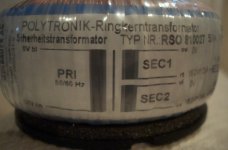
The trafo did not come with the kit, and I have a toroidal like this (the colors are in german language).
So here it is:
1 primary
Black 0
Brown 230
2 secondaries
Black 0
Red 18
Violet 0
White 18
How do I connect in the 3 pins of the DAC?
The trafo did not come with the kit, and I have a toroidal like this (the colors are in german language).
So here it is:
1 primary
Black 0
Brown 230
2 secondaries
Black 0
Red 18
Violet 0
White 18
How do I connect in the 3 pins of the DAC?
Attachments
black= +18V (DAC)
brown en black together = 0V (DAC)
red= -18V (DAC)
By the way I am using torodial transformers as well..
Regards,
Ronald
brown en black together = 0V (DAC)
red= -18V (DAC)
By the way I am using torodial transformers as well..
Regards,
Ronald
tingtong5 said:black= +18V (DAC)
brown en black together = 0V (DAC)
red= -18V (DAC)
By the way I am using torodial transformers as well..
Regards,
Ronald
Hi Ronald,
Black and brown are primaries, they go to mains, not to the dac... maybe you could revise your suggestion... Thanks in advance.
I re-post the colors scheme and the pic.
1 primary
Black 0
Brown 230
2 secondaries
Black 0
Red 18
Violet 0
White 18
Attachments

Kooka
You can try as follows:
Connect red to violet and measure AC voltage between black and white. If you get 36VAC then you can connect to the DAC boad as follows.
Red and violet together into the middle pin
Black and white each into the side pins
If you don't get 36VAC between black and white then I don't know. Do not connect it to the DAC board in that case.
quantran said:Kooka
You can try as follows:
Connect red to violet and measure AC voltage between black and white. If you get 36VAC then you can connect to the DAC boad as follows.
Red and violet together into the middle pin
Black and white each into the side pins
If you don't get 36VAC between black and white then I don't know. Do not connect it to the DAC board in that case.
Thanks quantran, that is what I thought.
Actually I get 41VAC (instead of 36) between black and white... would you connect or not?
Well, that would be 20.5-0-20.5V. I do not think that it would be a problem because the filter caps are rated at 50V. Just watch out if the LM317 and LM337 get too hot.
What the hell... I just tested another trafo of the same series I have on hand: should be 18-0-18 and it shows 41.5VAC... bad stuff, underrated. I will use anyway. Thanks, quantran.
Hi Kooka,
Sorry about that, must have been the hangover I had this morning from celebrating new year 🙄
Quantran is right connect red to violet and use black and white. A little higher voltage is no reason for concern.
Ronald
Sorry about that, must have been the hangover I had this morning from celebrating new year 🙄
Quantran is right connect red to violet and use black and white. A little higher voltage is no reason for concern.
Ronald
tingtong5 said:Hi Kooka,
Sorry about that, must have been the hangover I had this morning from celebrating new year 🙄
Quantran is right connect red to violet and use black and white. A little higher voltage is no reason for concern.
Ronald
😉
How can I squeeze more out of this Dac?
I'm glad I built this Dac. I've learned so much. It's musical and represents good value. But, if possible, I would like to match/exceed the performance of my Ah Tjoeb CDP. This may be unfair as this CDP retails for ~$1,200 USD. This CDP uses 6922/7308 Tube Buffer so I think it is a fair comparison. I've A/B'd these two DA converters using the Tjoeb as a transport. The Tjoeb puts out 2.5V and 250ohm Zout. I am using a TVC before my 1.5v sensitive 100K ohm 300B monoblocks. I'm using very low capacitance ICs. I've rotated 4 tubes: 6dj8/6922/6h23 variants.
My main issue when comparing these two sources is that the Tjoeb is more dynamic; it has more energy/drive/bloom in vocals but instruments as well. The Tjoeb has better HF extension and HF resolution and throws up a bigger soundstage, while the TDA1541's soundstage is more diffuse. These last two points (HF extension and soundstage) are not as important to me as the lack of energy/drive/dynamics compared to the Tjoeb.
My mods are posted in #627 on page 63. I have not modd'ed the power supplies, diodes, bypass caps for Dac pins to name a few possibilities. My I/V is set at 44R presently, and I guess I could increase it but then perhaps loose some transparency/detail which is not desirable.
I'm thinking about building a new tube stage, but short of this does anyone have any suggestions?
The main difference between this DAC and the Tjoeb is the fact that the Tjoeb still uses an opamp for I/V conversion and then uses the tubes for filtering and buffering. Also is has a TDA1545 DAC chip instead of a 1541.
My point is, it is a completely different beast...
My point is, it is a completely different beast...
Mike
You mentioned that you were going to try USB --> I2S connection. Have you tried it? The source of digital signal makes a big difference. If you use the CDP as a transport please try reclocking the DAC using the 74hc74 board. Without any jitter treatment the DAC is clearly in a weaker position compared to one box CDPs.
One characteristic of the tda1541a is that it sound very polite. That does not mean it lack dynamic. The dynamic capacity of my DAC is excellent. It handles very complex music with ease, no feeling of congestion at all. However the tda1541a is a little soft in the lower mid range and mid bass. Because of this it does not sound bold as BB's or AD's chips.
I also recommend that you change all the bypass caps. I have changed all to RIFA PHE426 series. My i/v resistor is only 33ohm only. I don't think it's a good idea to use high value I/V resistor. I've just also change the tube to Siemens (1958, RCA branded). I could not believe that these Siemens tube can make such a big difference.
Another thing that may sound strange to you is that I prefer LM317 and LM337 over the expensive Linear Tech regulators.
Cheers
Quan
Back to my trafo problems...
Back to my trafo problem, my next step was connecting the board to the trafo, and my problem is that the status led on sk8 does not light. My question is: does that led light only when working (seceiving signal from the reader, or should it light just connecting power? In this case I have a problem, I guess...
Back to my trafo problem, my next step was connecting the board to the trafo, and my problem is that the status led on sk8 does not light. My question is: does that led light only when working (seceiving signal from the reader, or should it light just connecting power? In this case I have a problem, I guess...
- Status
- Not open for further replies.
- Home
- Vendor's Bazaar
- Ultimate Twin TDA1541a Non-oversampling DAC with tube buffer & reclock set.......