It aint a few MHz any more, its hundreds, and with BGA's up to 1000 plus pins 3 or 4 voltages per chip, localised SMPS's DDR ram, gigabit ethernet etc, I've got to disagree, we handle RF frequencies on board every day, and the accociated problems of numerous ports switching at the same time. Moores law, etc that is why core voltages are down from 5V not many years ago to now in some cases 0.9V, ADC & DAC at 1.2V, so step size is minute compared to what it was, whan analoge sections had +/- 12 or 15V to play with. Its not a nice clean world any more its a dirty noisy pain in the unmentionable, with sub 1ns rise times. And yes most things aint repairable, it costs to much in time quite often, unless the value of the finished procuct warrants it.
I'm also curious as to what is classed as a mil spec pcb?
Marc🙂
I'm also curious as to what is classed as a mil spec pcb?
Marc🙂
Hi,
smd obviously can develop fast and complex circuits. my speech was referring to digital amplifiers.
sorry, I do not understand "mil spec PCB, perhaps another word? .
I develop PCB to 8 layers, but do not know this word.
Regards
smd obviously can develop fast and complex circuits. my speech was referring to digital amplifiers.
sorry, I do not understand "mil spec PCB, perhaps another word? .
I develop PCB to 8 layers, but do not know this word.
Regards
Hi AP2, didn't see you post, again the main drive for SMD is shrinking things down, you all want more power in your PC's etc, this is only possible by size reduction and more powerfull processors. As a side it does allow cheap throw away products, which in todays throw away soceities is a waste, quality always costs less in the long run.
But as I said one of the main drives in increased functionality, using less power and less space (though power density has increased).
One of the the main driver of throw away is peoples desires for mobile phones, that seem to go out of fashion in weeks!!!
I'm not a fan of this throw away culture. Electronics has been using surface mount devices reguraly for the last 25 years + so it isn't realy new.
As to a discrete class D, i wouldn't think it would sound any better so why do it, it seems a bit of a Luddite attitude to new (!) technology.
Mil spec these days is having your PCB made to IPC-6012 Class 3, I'm just curious when people refer to mil spec products wire etc, as the day of specific and very nic e components for military use are almost long gone, COTS has replaced specific mil and areospace products, due to financial as well as volume restraints.
Last edited:
Mil spec these days is having your PCB made to IPC-6012 Class 3, I'm just curious when people refer to mil spec products wire etc, as the day of specific and very nic e components for military use are almost long gone, COTS has replaced specific mil and areospace products, due to financial as well as volume restraints.
Ah..IPC-A-600 standard,yes I know,I work with it.
Retrurn at class d ,is my idea develop with small discrete an good class d also for DIY (with pcb) . but not selfoscillator. I want use hi-res modulator and two FB. 500KHz I think is very good.
Marc;
Your reasoning is perfectly sound - I am speaking from the viewpoint of a diy enthusiast who would like to build a design that can be fun to build and provide reasonable performance.
It looks like AP2, tiefbassuebertr. and myself are Luddites 🙂.
Your reasoning is perfectly sound - I am speaking from the viewpoint of a diy enthusiast who would like to build a design that can be fun to build and provide reasonable performance.
It looks like AP2, tiefbassuebertr. and myself are Luddites 🙂.
My appologies to both yourself Balaboo, AP2 and tiefbassuebertr; my use of the term Luddite was not personaly directed. I live and was braught up in the Pennines of Yorkshire and now live on the other side (still in the Pennines) so the term is used more coloquial around here. I live near mills that were featured in the folklore of Ned Ludd (it started I belive in Nottingham but soon spread 'up north'), now either appatments or supermarkets.
I was alluding more to the fact that though frequencies may not be high, it is the fast switching high current parts of class D circuitry that in my opinion and experience from laying out SMPS, class D, ADC/Delta sigma isolation, benefit greatly from the advantages SMD brings. Concise layout, small current loops, good EMC control, etc. It also has problems, heat concentration more Watts per square inch, hard for DIY construction, very process dependent with newer packaging types etc...
Again please accept my appologie Gentlemen, in my growing interest with class D, I still beg your indulgance to follow this thread.
I do repair work on guitar/PA systems, and let me tell you that the new breed of powered (active) speakers with built-in ClassD amplifiers are completely UNREPAIRABLE - cf. Behringer B212D, various Peavey and GVX units :-(.
I also repair PCs, including laptops - sorry, no fixee motherboard issues, especially on the Apple products.
Call me old-fashioned, but a "throwaway" approach galls me; I still do most of my own car repairs except those that require 'special' tools.
The hot air tool works great for those SMT components that expose their solder connections, but fails completely with BGA, etc. devices.
And I have designed and built RF amplifiers using standard mil-spec 2-layer PCB with through-hole components - please don't tell me kr*p like a few Mhz requires SMT,etc.
The main reason is compactness, and yes, radiation loops - I get the impression that most EE's seem to have lost the art and skill of high-frequency design AND implementation.
C'est la guerre !!
Hi balaboo,
the headaches of class D and traditional RF amps are not exactly the same.
In class D you have two main difficulties:
- Even if the switching frequencies are not very high, you have to handle very high di/dt in the power stage. 500A/us-1000A/us are quite normal.
Now consider a 10mm track, it might have 7nH. At 1000A/us you will already have a 7V peak caused by the inductance of a short track.
- Class D amps have to drive low impedances, the used switching power stages are low impedance circuits in the range of some ten mOhm. These impedances combined with typical parasitic loop inductances (10nH-50nH) and typical parasitic capacitances of MosFets are forming poorly damped RF-resonance circuits, again and again triggered by the switching events.
But I agree,these extreme conditions are in the loop:
Rail-MosFet-MosFet-Rail-supplycap.
The conditions in the driver stage are less demanding and I do not see a real reason for extremly small geometries - also not for high quality circuits.
Altogether you need to spend some love to the layout and proper RC(L)-snubbering of the switches. And you can reach stunning results even with TO-220.
Hello Chocoholic;
Good to hear from you - still in China ???
Your analysis spot-on; the output stage radiation loop is exactly what I was trying to draw attention to. And you are right about the layout issuse - I still have'nt been able to produce a working ClassD amplifier that does'nt blow the outputs in seconds :-(.
...I am back in good old Germany

Ohps, blowing the output within seconds is not funny.
This could have two reasons:
a) Overlap of gate drive signals? You may examine that without supply of the power stage, but auxiliary supplies for the drivers.
(In case of a self resonant topology you would have to feed a small signal from a signal generator to the comparator.)
If a) is fine - you may search for
b) Catastrophic resonances, which might be generated in the power stage and disturb the gate drive. You can examine this while powering the power stage with a small and current limited supply i.e. +/-12V , 500mA. Also during this examination it might be advantageous to use auxiliary supplies for all other circuit parts. The floating driver may be powered by a 12V photo battery, instead by the bootstrap.
In order to make sure that you see also fast resonances you should use a scope with 100MHz bandwidth at least.
In class D the traditional DIYapproach (draw a schematic, make a layout, build it - and then directly power up the entire thing with a strong supply) is usually not resulting in much success.
On the other hand, I am sure that you will get debugging support, if you go for an amp of reasonable complexity and reasonable power and post your headache.
Of course you would need to publish schematic and layout, your test set up, measurement set up etc. ...and post screen shots.
As far as I remember, in such cases the experienced guys around (and lady 😀 ) do give support.
Hi ,
selfoscillator certainly be catastrophic, especially if the frequency is high.
I'm testing a clock PWM (existing module) on a traditional two layers PCB with discrete drivers (4 bjet for jump) plus two DIP8 Mosfet-driver (currently TC4426).
400kHz, 50ns-DT. All resistors are 1/8W 1% ceramic. stability and sn / R is excellent, the problem is not that. Gerber also the public, how will they find exactly the same components to make it work perfectly?
The ideal would be to create a complete set of components and PCB (KIT).
I do not have time to handle this.
then put the Gerber and the wiring diagram e. .. good luck. 🙂(I just finished measures)
Regards
Hi,
I have been in the electronics industry for the past about 20 years. When I started SMD was VERY thin on the ground. Now days there is not much that I can get that is not SMD. We build with plenty of 0603 which I find is too small to read the numbers on. 1206 is plenty large enough and 0805 is still quite manageable with a soldering iron.
As a possible solution to the kit problem is to partly populate the PCB with the small SMD stuff and let Joe Public finish it off. This will only work for a minimum order of say 100 to 250. The problem there is with buying SMD parts is that they come on a reel. A small real is 4000 parts of 0603. This is way out of range for the DIY market.
Now for my actual question.
I am interested in building a Class D amp, but I find very little in the way of schematics on this site for this. I suspect that I will go the IRF route. Any suggestions? I can draw my own schematics and have laid out about 500 odd PCB in my existence thus far. I consider myself qualified, but will need to swat up a little on getting switch mode stuff working without generating heat.
Cheers
Hello wade99,
In this thread http://www.diyaudio.com/forums/class-d/167147-pqfn-5x6mm-packaged-n-channel-power-mosfet-classd.html I started work on an all smd class d amp, nothing fancy but still all smd.
Marce designed the PCBs and the schematic is borrowed from another thread here.
I got the PCBs done by a small company in Poland with the help of Markus2006.
If you follow the thread you can find usefull info.
The amp still needs to be assambeled and tested but it will be postponed because I am in the process of moving to another company.
Regards,
savu
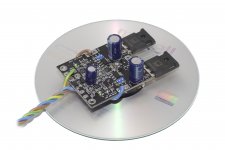
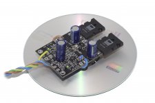
Supplement to post #6
about
Pro Audio - Miniature (M-Series) Power Amplifier Modules
http://www.proaudio.ltd.uk/Content/M-Series.pdf
I have found an additional board, that seems to be also without custom made front end IC's.
I hope, to hear resp. read more about the experiences concerning the audible differences (pros and cons) between all this topologies.
Which of this topologies have sonic character closest to the Pure Class-A Aleph and "First Watt" versions from Mr. Nelson Pass?
BTW - who knows a commercial brand, that offer amp devices or modules/units according the patent as follow?
http://www.sumobrain.com/patents/wipo/Ad-class-audio-amplifier/WO2006024739A1.pdf
unfortunately the describtion is in french.
Attachments
Last edited:
I have seen discrete class d amps, a search on google will bring them up.
Class D can be a bit of a minefield for novices.
I learned some hard lessons about class D like pcb layout and proper decoupling.
I did a semi discrete 2113 with a discrete op-amp trinagle wave generator into a comparator into XOR gates into a iR2113. Works quite well after a little work to fine tune it.
I am looking for a circuit collection and a collection of descriptions from the modules by post#6 and #36 and newer modules and ideas.
- Home
- Amplifiers
- Class D
- Ultimate sounded Class D for diy without custom made IC's like Tripath TA2020