First congratulations that you found the problem !What do you think ?
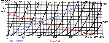
And Ra=39k , Rk=680Ω and Vb=275V looks very good on a E88CC.
Mona
Attachments
Not quite 275v as measured 266v.
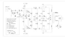
Schematic says 125v on plate but I only measure 88 v.
My fear is that preamp tube doesn’t amplify enough so the output tube KT77 would not deliver 25 watts.
What do you think ?
Any more measure I should take ?
Schematic says 125v on plate but I only measure 88 v.
My fear is that preamp tube doesn’t amplify enough so the output tube KT77 would not deliver 25 watts.
What do you think ?
Any more measure I should take ?
You need more or less 25Vtop to drive the output tubes to the max.
With 88V on the anode there is enough headroom for that.
Mona
With 88V on the anode there is enough headroom for that.
Mona
Thank you for your educated answer.
I’m still learning tube technology, being more used to transistor ;-)
That’s the fun part 🙂
I’m still learning tube technology, being more used to transistor ;-)
That’s the fun part 🙂
You need more or less 25Vtop to drive the output tubes to the max.
With 88V on the anode there is enough headroom for that.
Mona
When you say 88v on the anode, are you talking about the KT77 or the ECC88 ?
My measure of 88v is for the ECC88, preamp tube!
As I said, if they are not driven high enough, will the KT77 be under driven ?
Thanks
Changing R6 and R7 should do the trick. That biases the tube at lower idle current.
I would try 820 Ohms.
Cheers,
Ian
I would try 820 Ohms.
Cheers,
Ian
Changing R6 and R7 should do the trick. That biases the tube at lower idle current.
I would try 820 Ohms.
Cheers,
Ian
Why do you say that?
They are already at 680 ohms !
Attachments
Why do you say that?
They are already at 680 ohms !
Oh sorry my mistake 680 ohms that is 🙂)))
First congratulations that you found the problem !
And Ra=39k , Rk=680Ω and Vb=275V looks very good on a E88CC.
Mona
I finally tried R6 R7= 820 ohms
And R5 R8 = 24K
That gives 126 v on plate of b1a-b
The sound is very nice and the power is much better.
The only curious thing left are these :
P3 is supposed to adjust the AC balance using trimpot P3 by observing the output waveform until a symmetrical square wave without overshoots or dips is achieved. The square wave is about right, minus a bit of base lost but adjusting P3 has no effect at all.
Also, the left channel produces a bit more hummm than the right, volume off (resting state), and P4 reduces it but not enough, compared to right.
What do you think ?
Sorry to bother you again.
Did you see my previous message in which I am asking for your kind advice ?
Did you see my previous message in which I am asking for your kind advice ?
If there is more hum one side, first try exchanging tubes right/left does move the hum too.If not it's probably a layout fault, diff grounding ...
P4 is to get equal currents in the finals (same voltage over R14-R21).
P3 for balancing output AC drive.Put 100Ω beween C6 and ground, an earphone over that resistor and adjust for minimum sound (not to loud, stay in classA).
Since the cathode of one of the input triodes isn't grounded (for AC) is it a possible source of hum via the heater.Try connecting pin3 and 8 together (the cathodes), but the P3 has to be readjusted.
Mona
If there is more hum one side, first try exchanging tubes right/left does move the hum too.If not it's probably a layout fault, diff grounding ...
P4 is to get equal currents in the finals (same voltage over R14-R21).
P3 for balancing output AC drive.Put 100Ω beween C6 and ground, an earphone over that resistor and adjust for minimum sound (not to loud, stay in classA).
Since the cathode of one of the input triodes isn't grounded (for AC) is it a possible source of hum via the heater.Try connecting pin3 and 8 together (the cathodes), but the P3 has to be readjusted.
Mona
Premièrement: parlez-vous français? Moi si !
I studied your proposal and I have some questions.
Putting a 100 ohms between C6 is the same as R17 which is already at 26 volts!
I guess my earphone would not like it !!!
Connecting pin 3 and 8 together would not be advisable because it’s not the same circuit. It would interfere with the resistor-capacitor network between those 2 cathodes.
The left channel doesn’t have that problem and it’s built the same according to the schematic. So, I doubt the douce of humm is the heater.
A la mode de chez nous ? Un peu 😀Premièrement: parlez-vous français? Moi si !
Cutting the connection C6 - ground and puting 100Ω there to restore the connection gives no DC voltage.Putting a 100 ohms between C6 is the same as R17 which is already at 26 volts!
I guess my earphone would not like it !!!
It is the same circuit, the two triodes have the same current DC and AC, only AC in opposite phase.Connecting pin 3 and 8 together would not be advisable because it’s not the same circuit. It would interfere with the resistor-capacitor network between those 2 cathodes.
If the hum change sides along with the tubes, it is the heater, if not it's something else.The left channel doesn’t have that problem and it’s built the same according to the schematic. So, I doubt the douce of humm is the heater.
Mona
If the hum change sides along with the tubes, it is the heater, if not it's something else.
Mona[/QUOTE]
It doesn’t so it’s something else
Mona[/QUOTE]
It doesn’t so it’s something else
Cutting the connection C6 - ground and puting 100Ω there to restore the connection gives no DC voltage......
Oh that’s what you meant !!!
I didn’t get it at first.
I’ll try that !
Thanks
Oh that’s what you meant !!!
I didn’t get it at first.
I’ll try that !
Thanks
As stated in the schematic:
Adjustment of the DC balance (quiescent current of the output valves) is done by turning P4 as follows: completely turn down the volume control P1; connect the oscilloscope to the speaker output, with sensitivity 10 mV/div. A hum signal (100 Hz) is now visible which you can decrease to a minimum by adjusting P4. Minimum hum means equal quiescent currents. Repeat this for the other channel.
The humm I get is more related to that, not AC imbalance.
A la mode de chez nous ? Un peu 😀Cutting the connection C6 - ground and puting 100Ω there to restore the connection gives no DC voltage.It is the same circuit, the two triodes have the same current DC and AC, only AC in opposite phase.If the hum change sides along with the tubes, it is the heater, if not it's something else.
Mona
Finally, after another series of tests and trying your suggestions, nothing seems to change the bloody hummm. So if every part is ok then there must be something wrong with the configuration.
I probed with a very sensitive scope around to catch some spurious noise. As it was around 120 hertz, I figured it must be related to supply.
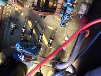
I remember I had to rearranged the fuse configuration because it was longer than the one suggested in the original kit.
It happens to come close to the pot P3 which is especially there to reduce imbalance between output tubes.
So I moved that fuse out of the way.
Problem solved !
That spot on the circuit is very high impedance so it catches any radiating frequency that may be around.
Now the amp has been set properly and audition tests will begin.
Thanks for everyone who helped me with suggestions.
One of them was especially helpful: do tests and measures then, apply fixes.
- Home
- Amplifiers
- Tubes / Valves
- UL40-S2 Van der Veen amp problem