I built that amp ordering the pc board and power supply tranformer. The rest of the components, I gathered by myself since the kit was no longer available. Once I first tested it, i had some problem with the power supply. The stan-by switch open, everything was fine. Once closed, R31 just blew. I was expecting Z2 to blow if there was a problem, but the opposite of the bridge gave that problem. I though C10 could be bad or any diode, but no, they tested OK. I can't think of a short anywhere on the circuit to cause that problem. This would have blown Z2. I tested any short anyway on the amp circuit and none.
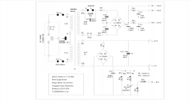
I suspected a reverse emf coming from the opposite sine wave of the transformer if the secondaries were reversed (sine+sine) but I could not test that condition. I'm out of idea but making R31 more powerful, since it's only half a watt. 3 watts maybe. But, I fear such action cause it's NOT supposed to have such amp going trough. I joined the schematics for your analysis and much welcome comments. Any advises ?
I suspected a reverse emf coming from the opposite sine wave of the transformer if the secondaries were reversed (sine+sine) but I could not test that condition. I'm out of idea but making R31 more powerful, since it's only half a watt. 3 watts maybe. But, I fear such action cause it's NOT supposed to have such amp going trough. I joined the schematics for your analysis and much welcome comments. Any advises ?
Attachments

That was my first thought. Actually, every single component tested ok. I doubted the power tube could be at problem. First, they are brand new. Second, they worked before. Third, they are connected with a center tap VO that is very high impedance (floating). I don’t see what power they could pull in a no signal situation.
The easiest to diagnose is to disconnect everything after the bridge. That'll give you immediate knowledge of where the issue is.
If the issue is gone, connect it again and disconnect everything after Vo, V1L, V1R. Alo, did you make any changes like the C12 value? You get the idea I guess.
Jan
If the issue is gone, connect it again and disconnect everything after Vo, V1L, V1R. Alo, did you make any changes like the C12 value? You get the idea I guess.
Jan
Last edited:
Everything up to Vo, V1L, V1R is ok. I know that would indicate something wrong in the amp section but there is no short nor any bad part.
What I don’t get is the R31 resistor blows but not the fuse in that circuit. I was suspecting a back emf from the heater circuit being connected in opposite phase. Contrary to the schematic, the 2 secondaries are not separate. I could get large voltage from grey, yellow, red meaning it’s one secondary with taps. And no C12 is perfectly fine.
What I don’t get is the R31 resistor blows but not the fuse in that circuit. I was suspecting a back emf from the heater circuit being connected in opposite phase. Contrary to the schematic, the 2 secondaries are not separate. I could get large voltage from grey, yellow, red meaning it’s one secondary with taps. And no C12 is perfectly fine.
there is no short nor any bad part.
The evidence implies otherwise.
What I don’t get is the R31 resistor blows but not the fuse in that circuit.
Obviously that is because the current that destroys R31 does not flow through the fuse. That is a good diagnostic indicator.
I was suspecting a back emf from the heater circuit being connected in opposite phase.
No idea what this means. Don't speculate, test and measure!
Contrary to the schematic, the 2 secondaries are not separate.
Please correct the schematic to reflect accurately the build. That is absolutely critical for diagnosing. If the two secondaries are connected and the GRY wire is connected to ground, there's your problem right there.
Jan
Last edited:

Mona was right. There was a short getting back from the heater secondary reversed ( my previous hypothesis on back emf). I corrected it, did many probe test, powered the plates sans heater, ad heater and powered everything. It works. Now, I played it and sounds good. Only have to correct the square wave distortion which is gonna be fun, compared to the power supply problem (I can measure things now). See the video next...
Thanks everybody for your advices
Thanks everybody for your advices
Serge, that sounds great!
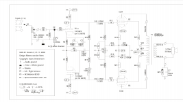
Still wondering on the main schematics though... I guess with proper matched powertubes it may be just theoretical, but still:
R17/C6: What happens when tubes get older and they wander a little off? I guess the bias will be different for both EL34... Is everything correctable with P4...
Still wondering on the main schematics though... I guess with proper matched powertubes it may be just theoretical, but still:
R17/C6: What happens when tubes get older and they wander a little off? I guess the bias will be different for both EL34... Is everything correctable with P4...
Last edited:
My guess is R17/C6 are there to limit the frequency range hence, block any oscillation. They affect the response curve. If the value changes, then the curve. In time, if sound appears different, a response test could be carry and values corrected to the original one. But I doubt it could come anytime soon...
Hummm on one channel
As everything works now the only left problem is a dull hummm on one channel, the other being very quiet...
I set the bias properly, checked bad parts but nothing found.
It’s obviously a 60 cycle humm but I can’t figured this out.
Any advice ?
As everything works now the only left problem is a dull hummm on one channel, the other being very quiet...
I set the bias properly, checked bad parts but nothing found.
It’s obviously a 60 cycle humm but I can’t figured this out.
Any advice ?
Attachments
Can you scope where it originates? Is it already at the input, driver output, output stage only? Do some diagnosis?
Where is the scope gnd clip connected to?
Because one channel is good, is there an obvious difference between channels in grounding, or ground wiring?
Is the input connector ground from both inputs connected to a ground somewhere? Have you tried to disconnect one of the input connector grounds to open the ground loop?
Also, what you show on the scope is typical power supply ground, so it is not from mains ground or mains earth. Typical this occurs when a power supply ground run is also used by a signal input ground run or speaker return ground run. If you scope with scope ground clip to input RCA ground, and the scope probe to the chassis ground, are you also seeing it then?
Jan
Last edited:
Sorry
Sorry, I was not clear.
I’m trying to set the bias so there is very few or no noise in the testing state (no input).
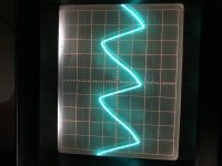
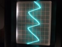
I put the scope in the speaker output, no signal, 10 mv. It should show a very weak signal (ambiant noise below hearing range) it does on left channel, 61 ma quiescent current.)
On right channel shown in the scope photo, a very strong 60 hertz humm is displayed, even though quiescent current is properly set. I was suspecting a ground loop but I cannot find the source. It’s like some parts of the heater supply radiate into the amp...
Sorry, I was not clear.
I’m trying to set the bias so there is very few or no noise in the testing state (no input).
I put the scope in the speaker output, no signal, 10 mv. It should show a very weak signal (ambiant noise below hearing range) it does on left channel, 61 ma quiescent current.)
On right channel shown in the scope photo, a very strong 60 hertz humm is displayed, even though quiescent current is properly set. I was suspecting a ground loop but I cannot find the source. It’s like some parts of the heater supply radiate into the amp...
Can you scope where it originates? Is it already at the input, driver output, output stage only? Do some diagnosis?
Where is the scope gnd clip connected to?
Because one channel is good, is there an obvious difference between channels in grounding, or ground wiring?
Is the input connector ground from both inputs connected to a ground somewhere? Have you tried to disconnect one of the input connector grounds to open the ground loop?
Also, what you show on the scope is typical power supply ground, so it is not from mains ground or mains earth. Typical this occurs when a power supply ground run is also used by a signal input ground run or speaker return ground run. If you scope with scope ground clip to input RCA ground, and the scope probe to the chassis ground, are you also seeing it then?
Jan
Attachments

- Status
- This old topic is closed. If you want to reopen this topic, contact a moderator using the "Report Post" button.
- Home
- Amplifiers
- Tubes / Valves
- UL40-S2 Van der Veen amp problem