Why is 25% screen tap best for EL84? In your response give a proof.🙂
cct = circuit
Acrosound made the UL model TO-310 transformer for use with 6V6 and EL-84 tubes. In the Keroes publication "Theory and Operation of the Ultra-Liear Circuit," he specified the 25% tap point for the 6V6 and the tap for other tubes of interest and said to anyone who wants to use those tap points and claim the UL title they needed a license to do so. Then when Hafler moved on to Dynaco the A-410 became the tranny to use for both of those tubes as well. The prescribed 6V6 tap point is also part of the Hafler/Keroes/Acrosound patent but generally described as approx. 5% of the primary Z. I'm going by the Keroes document since that is his claim for licensing.
Last edited:
You have done your homework, a very good response. I've seen & read several papers on the cct including those published in the early 50s. But don't recall ever seeing the paper on the 25% issue. Usually 43% was the favored number.
If you have a copy of that paper pls post it for us to read.
UL vs Screen Taps is a subject that should be left to English Majors to argue, if Hafler ever had a copyright on UL it has expired long ago. UL has simply become part of the language whether we like it or not. When UL is referred to we understand what is meant. And in a similar way distributed load, altho it would be wise to indicate if cathode FB is part of what the cct consists of.
Over many years I've built amplifiers with 10%, 20%, 43% & 50 % UL (or distributed load!!). My version of Norman Crowhurst's Twin Coupled Amp both 50% cathode FB & UL loading.
I've got quite a bit more info that I'll post later. The iNet is terrible here tonight, the Satellite connexion is poor. But could be the system is overloaded again, everything is running much slower with many folks stuck at home.
I've attached Williamson's paper 'Amplifiers & Superlatives' for all the keeners out there.
Attachments
This link got bumped on that last post so here it is again, this time from a different computer. Hope it works.🙂
Alan Blumlein - Wikipedia
Alan Blumlein - Wikipedia
You have done your homework, a very good response. I've seen & read several papers on the cct including those published in the early 50s. But don't recall ever seeing the paper on the 25% issue. Usually 43% was the favored number.
If you have a copy of that paper pls post it for us to read.
UL vs Screen Taps is a subject that should be left to English Majors to argue, if Hafler ever had a copyright on UL it has expired long ago. UL has simply become part of the language whether we like it or not. When UL is referred to we understand what is meant. And in a similar way distributed load, altho it would be wise to indicate if cathode FB is part of what the cct consists of.
Over many years I've built amplifiers with 10%, 20%, 43% & 50 % UL (or distributed load!!). My version of Norman Crowhurst's Twin Coupled Amp both 50% cathode FB & UL loading.
I've got quite a bit more info that I'll post later. The iNet is terrible here tonight, the Satellite connexion is poor. But could be the system is overloaded again, everything is running much slower with many folks stuck at home.
I've attached Williamson's paper 'Amplifiers & Superlatives' for all the keeners out there.
I'm not an electrical engineer (I am an IT engineer) so in simple terms what happens when a tap is wrong , say it needs 43% tap and you apply 20% instead and vice-versa. Until this thread I thought all UL taps were all 43% and that it was just a generic screen tap methodology. You guys all really know this stuff, I am impressed. Learning a lot and thanks!
I'm not an electrical engineer (I am an IT engineer) so in simple terms what happens when a tap is wrong , say it needs 43% tap and you apply 20% instead and vice-versa. Until this thread I thought all UL taps were all 43% and that it was just a generic screen tap methodology. You guys all really know this stuff, I am impressed. Learning a lot and thanks!
UL is an example of distortion cancellation. Usually when you apply feedback, distortion goes down proportionally with the amount of feedback you apply. More feedback = lower distortion. But when feedback is applied to a different grid from the input, strange things can happen. When you nudge the amount of feedback to some magic value, curvature in one part of the system can cancel out curvature in another part, giving you a sudden and deep null in distortion, over and above what first-approximation NFB theory would predict. Ul is aiming for that null.
This also means the optimum screen tap varies with the type of tube (and it's health) and with the operating conditions. i.e., with your choice of primary load impedance, which is also a function of your choice of supply voltage and operating class and... it could go on.
If you truly want to hit UL, you have to cut-and-try different feedback % while monitoring the distortion, or copy a proven design. If you can't be arsed with all that then you buy an off-the-shelf transformer which probably uses a generic 40%-ish tapping, and call it good enough for rock and roll.
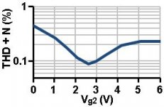
To give you an idea of what I mean, here's a picture of a cathode-coupled amp enjoying different amounts of feedback to the second grid. No prizes for spotting the distortion-calcellation null. OK it's not an output stage, but if you made a similar plot for an output stage with 0% screen feedback on the left (pentode mode) and 100% feedback on the right (triode mode) you'd get a similar sort of curve.
Attachments
Last edited:
UL is an example of distortion cancellation. Ul is aiming for that null.
This also means the optimum screen tap varies with the type of tube (and it's health) and with the operating conditions. i.e., with your choice of primary load impedance, ....
If you truly want to hit UL, you have to cut-and-try different feedback % while monitoring the distortion, or copy a proven design.
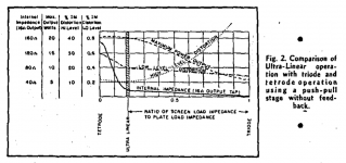
So if you want UL you have to understand what it provides vs. other screen tap points. Here is the plot for 6L6 and the Acro tranny designed for it, TO-300. Moving past the UL point you get more triode like results with lower power available and higher IM distortion.
Attachments
Last edited:
You have done your homework, a very good response. I've seen & read several papers on the cct including those published in the early 50s. But don't recall ever seeing the paper on the 25% issue. Usually 43% was the favored number.
If you have a copy of that paper pls post it for us to read.
UL vs Screen Taps is a subject that should be left to English Majors to argue, if Hafler ever had a copyright on UL it has expired long ago. UL has simply become part of the language whether we like it or not. When UL is referred to we understand what is meant.
I want to correct something in my prior post about the Smith article. It was actually Williamson that Hafler had the conflict with, specifically that Amplifiers and Superlatives article. Those differences were addressed in the Dec., 1953 Radio Electronics issue. I totally disagree with your assertion that the UL theory has to be absorbed into the uneducated mass (misconception). If you accept that idea then the benefit will be lost and forgotten. If you and I and anyone else knows the real story then we must keep it part of the hobby and history. It's worth its place and you may feel free to let it be a Q-Tip, but it really ain't. And when 99% of the posts we see refer to UL, they actually don't know what is meant because they don't know what it is.
Last edited:
The 1k resistor has twofold role:Quick question, if I have a power tube that is wired in the conventional configuration where I have a 1K resistor going to the screen from B+ and I want to convert it to UL at 40% tap, do I still need the 1K resistor or does the UL tap now go directly to the screen given that it is at 40% tap?
Thanks
1. Limits g2 current and its dissipation
2. Prevents RF oscillation just like the usual g1 grid resistor
Yes you need it even in UL configuration.
Some UL Items for Discussion
I chased down the Dec 53 copy of Radio Electronics magazine but came up empty on any reference to Williamson or Hafler. Is that the correct date? The file is an 18 MB pdf, lots of info current at that time, quite a bit on TV.
The Nov 1951 reference in Audio magazine is the earliest reference I am aware of for the UL cct application. Another article where UL is applied to the Williamson appears in the June 1952 issue.
The research lab I worked at in those days had a good technical library, that included periodicals. Audio magazine was one of those, very popular at that time.
An attachment here list links to many historical periodicals, a very good resource for anyone interested in electronics.
If I refer to building an SEUL amp using a 6LU8 I'm confident that 99% the readers will know what I'm referring too. It turns out I did about 10-15 yrs ago, it managed 6W Class A at clipping. 50% UL.🙂
Attachments
I chased down the Dec 53 copy of Radio Electronics magazine but came up empty on any reference to Williamson or Hafler.
Pg. 138. A screen tap does not UL make. I tried to pass on accurate info to someone and you want to interject and promote common misconception into the conversation. So you built an amp with a 6LU8 using a tranny with a screen tap... If someone has no concept of what UL theory and application is then they don't even know why a screen tap might be of any benefit, except for what they have heard in general terms. Woooohoooo! Drive a 6BQ5 with 43% and you get crap.... UL, no.
Last edited:
'Williamson and Frieborn incorrectly refer to the UL circuit as a feedback arrangement. This is not correct and it is simple to show why. In a feedback circuit the reduction in distortion and the reduction in internal impedance can never be greater than the reduction in gain. However, in the UL circuit there is practically no reduction of gain, but there is a significant reduction in distortion and internal impedance. Thus, there is a definitie advantage to the UL circuit since, as Williamson puts it, you get "something for nothing" and distortion can be made lower than either for triode or tetrode operation of the output tubes.' -HaflerI chased down the Dec 53 copy of Radio Electronics magazine but came up empty on any reference to Williamson or Hafler.
https://www.americanradiohistory.co...ronics/50s/1953/Radio-Electronics-1953-12.pdf
https://www.pearl-hifi.com/06_Lit_A...ol_01/Sec_02/081_Ultra-linear_Amps_w_Refs.pdf
With all I am learning about UL, I have an idea, would it be possible to run a pentode driver tube UL tapped coupling transformer to the power tube?
You could, but to what end? If you wanted to wire the power tube as a pentode or use the UL tap, you've now added another transformer in the first stage, so stability when you close the feedback loop will be nonexistent.With all I am learning about UL, I have an idea, would it be possible to run a pentode driver tube UL tapped coupling transformer to the power tube?
Pg. 138. A screen tap does not UL make. I tried to pass on accurate info to someone and you want to interject and promote common misconception into the conversation. So you built an amp with a 6LU8 using a tranny with a screen tap... If someone has no concept of what UL theory and application is then they don't even know why a screen tap might be of any benefit, except for what they have heard in general terms. Woooohoooo! Drive a 6BQ5 with 43% and you get crap.... UL, no.
Thankyou for your most considerate reply!🙂
I finally found Hafler's note, it is unfortunate that it was published on the last pages of a magazine directed toward the MRO (Maintenance, Repair & Overhaul) business. But that is where the referenced article is. A similar note in Audio Engineering might have been seen by more people who would appreciate what he was saying. Hafler's note is attached here for others to see.
Langford-Smith & Chesterman's article in the May 1955 Issue of Radiotronics (Australia) is a very good analysis of the basic circuit of the so-called UL or Partial Triode. The author's make the point that since there is no agreement on what to call the cct to them in the article it would be referred to as Ultra Linear or UL. Seems like that stuck, to me it has always been that. All the people I knew called it Ultra Linear. But audio was not my day job.
I hadn't seen that particular article altho the other circuits in Bill Perkins (PEARL) collection have been doing the rounds for many years. I made a point of meeting with Bill during a sales trip to Calgary about 30 yrs ago. I had seen some information on one of the rather exotic amplifiers he was building for sale. Among other things the cct used a NFB hookup from the output plates back to the screens of the PP voltage amplifiers. I built my own version but used a PP Differential Cascode stage, NFB to the upper grids. That way no grid current to drive
Bill showed me one of his projects, pulling together as many of the magazine articles on audio & associated circuitry minus the advertising text. At the time he wasn't too far along, looks like he has made great headway. Bill had a lot on the go, I think his biggest money maker is likely the tube coolers. I had been curious regards Norman Crowhurst's Twin Coupled Amplifier, Bill copied all three articles from his file for me. Much later I built my own version.
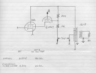
Around 1960 I thought, 'Why Not Electronic UL' , cathode followers driving the output stage screens. At the time the research project I was on used a lot of 6DQ5s. When hard driven it was possible to drive 1.5A pulses down a transmission line, something we needed. The 6DQ5 screens run at lower voltage so that seemed like a possibility. I got as far as some preliminary tests on 6V6s, but all seemed too complicated for the results. Somehow one of my original sketches survives. Attached here for the curious. Much later, about 20 yrs ago I found a tapped OPT meant for educational applications. It looked perfect to do many tests. But another money maker contract appeared & away I went. Think it was Lundahl, but not sure.
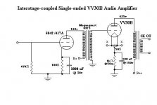
The SE partial triode 6LU8 cct is also attached so all are free to trash it. It is very different authoring for publication an article in a magazine directed to a widely diversified audience when compared to preparing an engineering report or a sales proposal.🙂
Attachments
Thank you Mr. Stewart. I thoroughly enjoy your posts. I think you should write a book to preserve all these interesting bits of history.
Does anyone know what the UL tap is for a 50L6?
The default Edcor tap is 40%
also the schematic shows a 2.2K screen resistor at 120V B+ but I will be applying 188V B+
So I need to change it to 188/120 = 1.5 so 2.2K* 1.5 = 3.5K correct?
The default Edcor tap is 40%
also the schematic shows a 2.2K screen resistor at 120V B+ but I will be applying 188V B+
So I need to change it to 188/120 = 1.5 so 2.2K* 1.5 = 3.5K correct?
Last edited:
It is very unlikely that anyone has determined the UL sweet spot for the 50L6 family (12L6, 25L6, 6W6). But as a guide to determine cathode bias required to limit the B+ dissipation, use the 6W6 triode curves to find the value of a cathode bias resistor. The 40% tap would be OK, that is still a very good feedback factor to enable the tube to drive a non-linear loudspeaker load.
A few years back I hot rodded the 50L6 output stage in an old AA5 AC/DC receiver. I used it as subject matter for a presentation at our local vintage radio club.🙂
A few years back I hot rodded the 50L6 output stage in an old AA5 AC/DC receiver. I used it as subject matter for a presentation at our local vintage radio club.🙂
Attachments
- Home
- Amplifiers
- Tubes / Valves
- UL conversion