Here is my current amps.
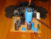
4 Gainclones using lm3886 each with 2 x 1000 uf silmic and 300 VA 25V AC.
The small prints hold a double bridge mur860 for each channel.
Isolation pads are to layers of normal paper. And it kinda of works, the heatsinks can actualy get a little warm.
Note that the amp is place on a sheet of paper to make it more moveable.
Left channel:
Attachments

thus, don't judge a book by it's cover? 😉
(dang man, take some sandpaper to the case and some paint and
it would look fine. such pretty insides!)
(dang man, take some sandpaper to the case and some paint and
it would look fine. such pretty insides!)
Hey, I recognize that heatsink that Fleming J P uses.
It's out of a Sansui amplifier. I have an AU707 amp with the same heatsink, only difference is that the Sansui ones were black anodized.
Perhaps Fleming's heatsink is factory?
It's out of a Sansui amplifier. I have an AU707 amp with the same heatsink, only difference is that the Sansui ones were black anodized.
Perhaps Fleming's heatsink is factory?
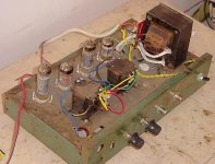
Yup, it's ugly. Don't change it a bit.corbato said:This gotta win the most ugly amp award here. 😎 A 6BQ5 affair which sounds heavenly. Spent very little money - mostly on the passive components. Everything else was salvaged. Working fine even now.
Have you got a 6BQ5 amp schematic that you could post?
Here we are ..sir 6BQ5 SE Schematicpaulb said:
Yup, it's ugly. Don't change it a bit.
Have you got a 6BQ5 amp schematic that you could post?
Thanks, Ashok. Nice site, lots of stuff there to look at. I don't know if I will ever build a tube amp, but I have some 6BQ5s.
An externally hosted image should be here but it was not working when we last tested it.
An externally hosted image should be here but it was not working when we last tested it.
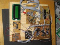
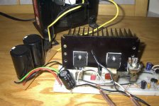
2x LM3886 running -+30volt rails from a switch mode power supply. The power supply is a hybrid of the two supplys on www.sound.au.com and some stuff from the data sheet.
The vast majority of the parts came either from the amp that once inhabited the chassis or from old monitors...TVs...etc. Got to love good ol student engineering.
works though and is only used on the midbasses in my car.
Look, it's almost as nice as Peter Daniel's work ... ok, maybe not 😀. I just made this as a prototype for a case I hope to make in aluminium for the little amp. Topic here.
Front shot 1:
Front shot 2:
Audio-grade power connector :
:
Front shot 1:
An externally hosted image should be here but it was not working when we last tested it.
Front shot 2:
An externally hosted image should be here but it was not working when we last tested it.
Audio-grade power connector
:An externally hosted image should be here but it was not working when we last tested it.
SPEC-2?
What's this? A famous Pioneer SPEC-2?
Oh wait, that back panel doesn't look right.
How about the inside?
What's this? A famous Pioneer SPEC-2?
An externally hosted image should be here but it was not working when we last tested it.
An externally hosted image should be here but it was not working when we last tested it.
Oh wait, that back panel doesn't look right.
An externally hosted image should be here but it was not working when we last tested it.
An externally hosted image should be here but it was not working when we last tested it.
How about the inside?
An externally hosted image should be here but it was not working when we last tested it.
An externally hosted image should be here but it was not working when we last tested it.
An externally hosted image should be here but it was not working when we last tested it.
More details
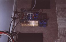
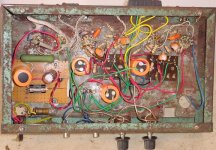
(No its not a Pioneer, though someone did give me the faceplate)
Specifications-
Year made - 1989 (my 1st DIY project! right out of college)
No. of Output Transistors - 6 per channel (actually 4 per channel are for the output.....I think the other 2 drive them...but who knows?)
Power Output - 20 volts p-p into 2 ohms (10 amps) (found a few measurements)
VCC - plus and minus 40 volts
Fan- high, low, off, selected by switch on right of back panel
Inputs- RCA or clip-post, selected by switch on left of back panel (2nd pic below)
No. of Transformers for output stage- 2
No of power supplies - 2 (separate PS for input circutry, the black rectangle next to the perfboard)
Rectifier- I can't find it, must be under the caps. Its a super high power ceramic jobbie that cost about $25 in 1989.
Expansion- DIN connector to connect external capacitance.
No. of LEDs, - 2 (shining into the meters)
- This is kind of an embarrassing post, but this thing actually worked; I took it out of the box this morning to take photos, note the dust!
Think I can bring this into the new millenium?
An externally hosted image should be here but it was not working when we last tested it.
An externally hosted image should be here but it was not working when we last tested it.
An externally hosted image should be here but it was not working when we last tested it.
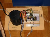
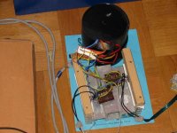
here is my ugly amp.
i used a box from an old scooter speed controller.
I put the coke can there for size comparison, and the pocket TV has a battery pack taped to it, that powers the old PS2 cooling fan.
it was going to be a briged lm3886, but its now a single lm3886, because my second chip, I had to run wires from the chip to the perfboard, and the pins 1 through 11, I had backwards!!!
pin 1 was pin 11, and pin 2 was pin 10, and so on so on,
oops. the chip got really really hot, and didnt smell good.
i pulled it out, and put the other one in place of it, soldering the wires on the right way this time. it worked.
im afraid to try that chip again, i think overture and spike didnt save this one!. its prolly dead.
Attachments

I don't feel so ashamed now. The circuit I am currently building will have be in an old packerd bell desktop computer case. Since I have little money to spend on this project, it is as good as it is going to get, all complete with some recycled parts too. At least the case is made from metal....a little RF shielding never hurts.
- Home
- Amplifiers
- Solid State
- UGLY Looking Amp! - but good working